WHEEL BEARING ADJUSTMENT Automatic Locking Hub 1. Raise and support vehicle. Remove front wheels. Remove retainer washers from lug nut studs and remove automatic locking hub assembly from spindle. See AUTOMATIC LOCKING HUBS under REMOVAL & INSTALLATION. 2. Using Lock Nut Wrench (T70T-4252-B) or 2 3/8" hex lock nut wrench, loosen wheel bearing adjusting nut. While rotating hub and rotor assembly, tighten adjusting nut to 35 ft. lbs. (47 N.m) to seat bearings. Spin rotor and back off nut 1/4 turn (90 degrees). Retighten adjusting nut to 16 INCH lbs. (1.8 N.m). 3. Align closest lug in wheel bearing adjusting nut with center of spindle keyway slot. Advance nut to next lug if necessary. Install locking key in keyway under adjusting nut. Install locking hub assembly. Final end play of hub on spindle should be .000-.003" (.00-.08 mm). Torque required to turn hub and rotor assembly should not exceed 25 INCH lbs. (2.8 N.m). Install wheels.
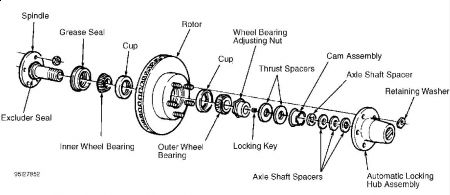
AUTOMATIC LOCKING HUBS Removal 1. Raise and support vehicle. Remove front wheels. Remove retainer washers from lug nut studs and remove automatic locking hub assembly from spindle. SeeFig. 3 . Remove snap ring from end of spindle shaft. Remove axle shaft spacer. Being careful not to damage plastic moving cam or thrust spacers, pull cam assembly off wheel bearing adjusting nut, and remove 2 plastic thrust spacers from adjusting nut. 2. Using a magnet, remove locking key. It may be necessary to rotate adjusting nut slightly to relieve pressure against locking key before key can be removed. CAUTION: DO NOT pry on cam or spacers during removal, as it may damage cam or spacers. CAUTION: To prevent damage to spindle threads, look into spindle keyway under adjusting nut and remove separate locking key before removing adjusting nut (if necessary).Installation To install, reverse removal procedure. Ensure cam assembly key is aligned with spindle keyway. Ensure automatic locking hub assembly legs are aligned with 3 cam assembly pockets. Final end play of hub on spindle should be .000-.003" (.00-.08 mm). Torque required to turn hub and rotor assembly should not exceed 25 INCH lbs. (2.8 N.m).
Jun 6, 2009 at 10:42 AM