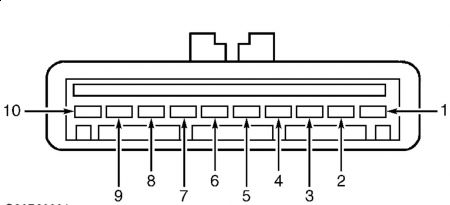
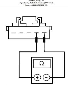
CRUISE CONTROL INOPERATIVE 1. Remove splash shield from throttle linkage. Ensure actuator cable is properly connected to throttle body and speed control servo. Pull on cable at throttle linkage side and note accelerator pedal movement. Check for smooth operation of cable. Correct as necessary and test operation. 2. Unplug harness connector from servo located near master cylinder. Turn ignition to run position. Measure voltage between servo harness connector terminal No. 7 (Light Blue/Pink wire) and terminal No. 10 (Black wire). See Fig. 1 . If battery voltage is present, go to step 4 . If battery voltage is not present, check fuse No. 5. Replace fuse if necessary. If fuse is okay, go to next step. Fig. 1: Identifying Servo/Actuator Harness Connector Terminals 3. Turn ignition off. Measure resistance between harness connector terminal No. 10 (Black wire) and ground. If resistance is less than 5 ohms, repair Light Blue/Pink wire. If resistance is 5 ohms or greater, repair Black wire to ground. See WIRING DIAGRAMS . 4. With brake pedal released and ignition off, measure voltage between servo harness connector terminal No. 4 (Tan/Light Blue) and terminal No. 10 (Black wire). If no voltage is present, go to next step. If voltage is present, install new BPP switch and check system for normal operation. 5. Turn ignition off. Measure resistance between servo harness connector terminal No. 4 (Tan/Light Blue) and terminal No. 10 (Black wire). If resistance is less than 20 ohms, go to next step. If resistance is 20 ohms or greater, go to step 15 . 6. Measure voltage between servo harness connector terminal No. 9 (Black/Yellow wire) and terminal No. 10 (Black wire). If battery voltage is not present, go to next step. If battery voltage is present, go to step 9 . 7. Unplug connector from brake pressure switch, located on master cylinder. Measure resistance between switch terminals with brake pedal released. If resistance is less than 5 ohms, go to next step. If resistance is 5 ohms or greater, replace switch and check system for normal operation. 8. Measure voltage between brake pressure switch harness connector terminal (Light Green/Red wire) and ground. If battery voltage is present, repair open in Black/Yellow wire. If battery voltage is not present, repair open in fuse or Light Green/Red wire between fuse and switch. See WIRING DIAGRAMS . Check system for normal operation. 9. Check for voltage between servo harness connector terminal No. 5 (Light Blue/Black wire) and terminal No. 10 (Black wire). If voltage is present, speed control actuator switch is stuck on. Install new speed control actuator switch and check for normal system operation. See COMMAND SWITCHES under REMOVAL & INSTALLATION. If no voltage is present, go to next step. 10. With speed control ON switch depressed, check for voltage between servo harness connector terminal No. 5 (Light Blue/Black wire) and terminal No. 10 (Black wire). If voltage is present, go to step 13 . If no voltage is present, go to next step. 11. Disable air bag restraint system. See AIR BAG RESTRAINT SYSTEMS article. Disconnect air bag sliding contact connector at base of steering column. Measure resistance of Dark Green/Orange wire between servo harness connector terminal No. 6 and air bag sliding contact connector (harness side). If resistance is less than 5 ohms, go to next step. If resistance is 5 ohms or greater, repair open or high resistance in Dark Green/Orange wire. See WIRING DIAGRAMS . Check system for normal operation. 12. With Driver's air bag module removed, measure resistance of air bag sliding contact between column side of connector at base of steering column and sliding contact. Connect one ohmmeter lead to connector terminal corresponding to Light Blue/Black wire in harness side of connector, and other ohmmeter lead to appropriate sliding contact pin. See WIRING DIAGRAMS . If resistance is less than 1 ohm, install new speed control actuator switch and check system for normal operation. See COMMAND SWITCHES under REMOVAL & INSTALLATION. If resistance is one ohm or greater, replace air bag sliding contact and check system operation. See AIR BAG RESTRAINT SYSTEMS article. 13. While depressing SET/ACCEL button on steering wheel, measure resistance between servo harness connector terminal No. 5 (Light Blue/Black wire ) and terminal No. 6 (Dark Green/Orange wire). Resistance should be between 640 ohms and 720 ohms. If resistance is as specified, go to next step. If resistance is not as specified, install new speed control actuator switch and check system for normal operation. See COMMAND SWITCHES under REMOVAL & INSTALLATION. 14. Test drive vehicle and observe speedometer operation. If speedometer operates properly, repair circuit (Gray/Black wire) between servo connector terminal No. 3 and PCM 104-pin connector terminal No. 68. See WIRING DIAGRAMS . If speedometer does not operate properly, see INSTRUMENT PANELS article. 15. Turn igniton off. Disconnect Brake Pedal Position (BPP) switch. Measure resistance between BPP switch harness connector terminal No. 1 (Black/Pink wire) and ground. If resistance is less than 5 ohms, go to next step. If resistance is 5 ohms or greater, repair Black/Pink wire between BPP switch and ground connection. See WIRING DIAGRAMS . Check system for normal operation. 16. Measure resistance between BPP switch terminals No. 1 and No. 2. See Fig. 2 . If resistance is less than 5 ohms, go to next step. If resistance is 5 ohms or greater, install new BPP switch and check system for normal operation. Fig. 2: Testing Brake Pedal Position (BPP) Switch Courtesy of FORD MOTOR CO. 17. Disconnect Clutch Pedal Position (CPP) switch or jumper. Measure resistance of Red/Light Green wire between CPP connector and BPP connector. If resistance is less than 5 ohms, go to next step. If resistance is 5 ohms or greater, repair Red/Light Green wire or connections and check system operation. See WIRING DIAGRAMS . 18. Measure resistance of Tan/Light Blue wire between CPP connector and speed control servo connector terminal No. 4. See Fig. 1 . If resistance is less than 5 ohms, install new CPP switch or jumper. If resistance is 5 ohms or greater, repair Tan/Light Blue wire or connections and check system operation. See WIRING DIAGRAMS .
12/13/2009 ...
Dec 13, 2009 at 8:29 AM