ENGINE CRANKS BUT WILL NOT STARTCheck fuel tank contents and fuel gauge accuracy. Check for dirt, water or other contamination in fuel. Check ignition system for strong secondary current at spark plugs. If no spark exists or is weak, repair ignition system problem first. Check fuel lines and fittings for leaks. If no leaks are found, check fuel delivery system for proper pressure and volumes. Reset inertia switch if necessary. Check for a defective fuel injector or coolant temperature sensor. Ensure TPS is not sticking.
INJECTOR CHECK Connect tachometer to engine. Run engine at idle. Disconnect and reconnect injectors individually. If engine speed drops at least 100 RPM momentarily, injectors are okay. RPM drop should only be momentary as ISC will attempt to re-establish correct idle RPM. Replace any injectors that do not cause sufficient drop in engine speed. When test is complete, turn engine off. To check curb idle, refer to emission control specifications on decal in engine compartment or SERVICE & ADJUSTMENT SPECIFICATIONS article.
INJECTOR CIRCUIT Disconnect all injector harness connectors. Using digital ohmmeter, check resistance across terminals of each injector. See INDIVIDUAL PFI INJECTOR RESISTANCE .INDIVIDUAL PFI INJECTOR RESISTANCEEngineOhms2.3L & 3.0L15.0-18.02.9L, 4.0L, 4.9L, 5.0L & 5.8L
INERTIA SWITCH In event of a collision, electrical contacts in inertia switch open and fuel pump automatically shuts off. Fuel pump will shut off even if engine does not stop running. Engine will stop due to lack of fuel. It is not possible to restart engine until inertia switch is manually reset, which is accomplished by depressing the switch button. See INERTIA SWITCH LOCATION .
INERTIA SWITCH LOCATION Application Location Aerostar On right kick panel, adjacent to front passenger's seat Bronco II & Ranger On floor board, right of transmission hump Bronco & "F" Series On left kick panel, near emergency brake pedal "E" Series Passenger's side cowl panel.
THICK FILM IGNITION IV (TFI) IGNITION SYSTEM CHECKSSPARK CHECK Using a high output spark tester, check for spark at coil wire while cranking engine. If spark is present, go to step 2). If spark is not present, remove distributor cap and crank engine to check for distributor rotation. If okay, check coil secondary wire resistance. Resistance should be no greater than 7000 ohms per foot. Place transmission in Neutral. Disconnect TFI wiring harness connector. Attach TFI Ignition Tester (105-000003). Connect Red lead of tester to 12 volts. Attach remote starter to "S" terminal of starter relay. Crank engine with remote starter while observing 2 LED lights on tester. If the PIP light blinks, go to step 4). If not, remove distributor. Remove TFI module from distributor. Using an ohmmeter, ensure all circuit resistance values are correct. See Fig. 4.
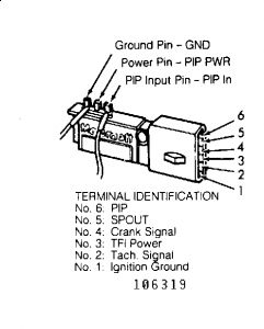
. See TFI MODULE CIRCUIT RESISTANCE SPECIFICATIONS . If readings are incorrect, replace TFI module. If readings are correct, check stator for open winding or short to ground. See SYSTEM/COMPONENT TESTS article in this section. TFI MODULE CIRCUIT RESISTANCE SPECIFICATIONSTFI Terminals (1) Ohms Ground Pin - PIP More than 500Power Pin - PIP Input Pin Less than 2000Power Pin TFI Power Less than 200Ground Pin - Ignition Ground Less than 2PIP Input Pin - PIP Less than 200(1)See Fig. 4 for terminal identification. If TACH light did not blink in step 2), replace TFI module and repeat step 1). If spark is still not present, replace ignition coil and module connector. If the TACH light did blink in step 2), substitute ignition coil with a known working unit and repeat step 1). If spark is now present, verify coil secondary wire resistance is no greater than 7000 ohms per foot and replace ignition coil. If spark was not present in step 4), connect original vehicle coil and spark tester. Remove pin-in-line connector located near distributor. Crank engine while checking for spark. If spark is present, inspect PIP and ignition ground circuits to verify continuity. See Fig. 2 and Fig. 3 . Repair as necessary.
Fig. 2: TFI System Schematic (W/O Computer Controlled Dwell)
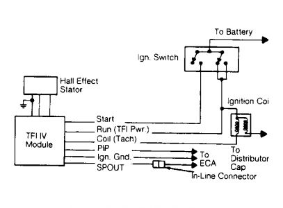
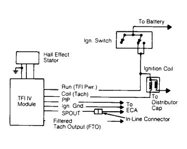
Fig. 3: TFI System Schematic (W/ Computer Controlled Dwell)
If spark was not present in step 5), measure battery voltage with negative lead from volt meter attached to base of distributor. Measure voltage at ignition coil positive (+) terminal. Ignition coil positive (+) terminal voltage should be at least 90 percent of battery voltage. If not, check circuitry between ignition coil and ignition switch for wear or damage. Repair as necessary. If ignition coil positive (+) terminal voltage was at least 90 percent of battery voltage in step 6), remove connector from ignition module. Disconnect starter relay "S" terminal. Turn ignition on. Measure voltage at ignition module connector power terminals No. 3 and 4. See Fig. 4 . See TFI MODULE VOLTAGE TEST TERMINALS .Voltage should be at least 90 percent of battery voltage. If not, check circuitry between ignition coil and ignition switch for wear or damage. Repair as necessary. If voltage was at least 90 percent of battery voltage in step 7), inspect wiring between ignition module terminal No. 2 and coil. If okay, check all related circuitry. Replace or repair as necessary.
TFI MODULE VOLTAGE TEST TERMINALSTFI Terminal Ignition Switch Position With CCD (1) : No. 3Run & Start Without CCD (1) No. 3Run & Start No. 4Start(1)Computer Controlled Dwell.
DIS IGNITION SYSTEM CHECK - NO START (2.3L)DISTRIBUTORLESS IGNITION SYSTEM (DIS) - NO START CHECK (2.3L)NOTE: The following diagnostic tests are in sequence. Begin with the first test and complete each successive test. DO NOT skip tests unless directed. TEST 1, CHECK ECA FOR FAULT CODES Repair as necessary. See TESTS W/CODES article. If no fault codes are retrieved, proceed to TEST 2.TEST 2, CHECK FOR SPARK DURING CRANK Using Neon Bulb Spark Tester (D89P6666 A), check for spark at each right side spark plug wire while cranking. If spark is present on all right side spark plug wires and consistent, (one spark per crank revolution), go to test 3). If spark is not present or consistent, go to TEST 5.TEST 3, CHECK DIS MODULE PIP OUT Install diagnostic cable. Connect diagnostic cable to breakout box. Use 2.3L overlay. Connect LED test lamp between (+) J31 (PIP EEC) and (-) J60 (BAT-). Crank engine. Does LED test lamp blink continuously during cranking? If yes, go to TEST 4. If no, replace DIS module and check for fault codes. See TESTS W/CODES article.
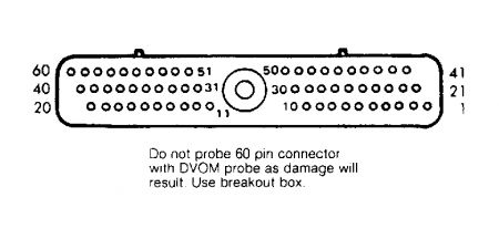
TEST 4, CHECK PIP OUT CONTINUITY With key off, disconnect ECA. With an ohmmeter, measure resistance between Pin No. 56 of the ECA vehicle harness connector and J31 (PIP EEC). See Fig. 5 . If resistance is less than 5 ohms, refer to the TESTS W/CODES article, PINPOINT TEST A in this section. If resistance is more than 5 ohms, service open circuit, reconnect ECA and check for fault codes. See TESTS W/CODES article.
TEST 5, DETERMINE MISSING SPARK COMBINATIONDuring cranking, is spark missing from both cylinders No. 1 and 4, or is spark missing from both cylinders No. 3 and 2 plug wires? If spark is missing, go to TEST 7. If spark is present, go to TEST 6.TEST 6, CHECK PLUGS & WIRESCheck spark plug wires for insulation damage, looseness, shorting or other damage. Remove and check spark plugs for damage, wear, carbon deposits and proper plug gap. If spark plug wires and spark plugs are good, reinstall and go to TEST 7. If components are faulty, service or replace as required. Check for fault codes. See the appropriate TESTS W/CODES article.TEST 7, CHECK DIS MODULE VBATInstall diagnostic cable. Connect diagnostic cable to breakout box. Use the 2.3L overlay. connect LED test lamp between (-) J2 (IGN D) and (+) J5 (VBAT D). Turn key on. Is LED test light on? If yes, go to TEST 8. If not, check connectors, service or replace harness and check for fault codes. See TESTS W/CODES article.TEST 8, CHECK DIS MODULE IGNITION GROUNDWith key off, check resistance between J2 (IGND-D) and J60 (BAT-). If resistance is less than 5 ohms, go to TEST 10. If resistance is more than 5 ohms, go to TEST 9.
TEST 9, CHECK DIS MODULE MOUNTING SCREWSCheck DIS module mounting screws for corrosion or looseness. If mounting screws are clean and tight, replace DIS module and check for fault codes. See TESTS W/CODES article. If screws are not clean and tight, clean or replace screws. Clean mounting area on DIS module. Check for fault codes. See TESTS W/CODES article.TEST 10, CHECK RIGHT COIL PACK CIRCUITSWith key on, connect LED test light between (+) J18 (RC1D) and (-) 60 (BAT-). Does LED test light illuminate? Connect test lamp between (+) J10 (RC2D) and (-) J60 (BAT-). Does LED test light illuminate. If test light illuminates in both tests, go to TEST 14. If test light does not illuminate in both tests, go to TEST 11.TEST 11, RIGHT COIL PACK FAULT, ISOLATE DIS MODULE With key off, disconnect diagnostic cable connector from DIS module (Pins No. 7-12). See Fig. 6 . Repeat test procedures in TEST 10. If test light illuminates during both tests, replace the DIS module and check for fault codes. See TESTS W/CODES article. If test light does not illuminate during both tests, go to TEST 12.
TEST 12, CHECK RIGHT COIL PACK VBATConnect LED test light between (+) J26 (VBAT R) and (-) J60 (BAT-). Does LED test light illuminate. If yes, go to TEST 13. If no, check connectors, service or replace the harness, check for fault codes. See TESTS W/CODES article.TEST 13, CHECK RIGHT COIL CIRCUITConnect LED test light between (+) J23 (RC1C) and (-) J60 (BAT-). Does test light illuminate? Connect LED test light between (+) J24 (RC2C) and (-) J60 (BAT-). Does test light illuminate? If test light illuminates during both tests, one or both coil wires are shorted to VBAT. Service connectors and harness and check for fault codes. See TESTS W/CODES article. If test light does not illuminate during both tests, replace right coil pack and check for fault codes. See TESTS W/CODES article.TEST 14, CHECK PIP D AT DIS MODULEConnect LED test light between (+) J32 (PIP D) and (-) J60 (BAT-). Crank engine. If test light blinks continuously during crank, go to TEST 15. If test light does not blink continuously during crank, go to TEST 19.TEST 15, CHECK DIS MODULE COIL DRIVERSConnect LED test light between (+) J18 (RC1D) and (-) J60 (BAT-). Crank engine. Does test light blink continuously during crank? Connect test light between (+) J10 (RC2D) and (-) J60 (BAT-). Crank engine. Does test light blink continuously during crank? If test light blinks continuously during both tests, go to TEST 16. If test light does not blink continuously during both tests, replace the DIS module and check for fault codes. See TESTS W/CODES article.
TEST 16, CHECK RIGHT COIL PACK VBATConnect LED test light between (+) J26 (BAT R) and (-) J60 (BAT-). Does test light illuminate. If yes, go to TEST 17. If no, check connectors, service or replace the harness and check for fault codes. See TESTS W/CODES article.TEST 17, CHECK RIGHT COIL CIRCUITConnect LED test light between (+) J23 (RC1C) and (-) J60 (BAT-). Does test light illuminate? Connect test light between (+) J24 (RC2C) and (-) J60. Does test light illuminate? If test light illuminates in both tests, go to TEST 18. If test light does not illuminated in both tests one or both coil wires is shorted to ground or the coil pack may be damaged. Check connectors, service or replace the harness. Check for fault codes. See TESTS W/CODES article.TEST 18, CHECK RIGHT COIL CIRCUITRepeat test procedures in TEST 17 and crank engine during each test connection. Does test light blink continuously during each test. If yes, replace the right coil pack and check for fault codes. See TESTS W/CODES article. If test light does not blink continuously during each test connection, one or both coil wires are open. Check connectors, service or replace harness. Check for fault codes. See TESTS W/CODES article.TEST 19, ISOLATE DIS MODULE FROM PIP DWith the key off, disconnect diagnostic cable connector from DIS module (Pins No. 1-6). See Fig. 6 . Connect LED test lamp between (+) J32 (PIP D) and (-) J55 (IGND S). Crank engine. Does test light blink continuously while cranking engine? If yes, go to TEST 26. If no, go to TEST 20. TEST 20, CHECK CRANKSHAFT SENSOR VBATWith key on, connect LED test lamp between (+) J56 (VBAT S) and (-) J (IGND D). Is LED test light illuminated. If yes, go to TEST 21. If no, check connectors. Service or replace harness. Check for fault codes. See TESTS W/CODES article.TEST 21, CHECK CRANKSHAFT SENSOR IGNITION GROUNDWith key off, disconnect ECA. Disconnect diagnostic cable connector from crankshaft sensor. Connect ohm meter between J55 (IGND S) and J60 (BAT-). Is resistance less than 5 ohms? If yes go to TEST 22. If no, check connectors, service or replace harness. Check for fault codes. See TESTS W/CODES article.TEST 22, CHECK CRANKSHAFT SENSOR PIP SConnect ECA. Connect diagnostic cable connector to crankshaft sensor. Connect LED test lamp between (+) J33 (PIP S) and (-) J2 (IGND D). Does LED test light blink continuously while the engine is cranked. If yes, PIP is open between sensor and DIS module. Check connectors, service or replace the harness. Check for fault codes. See the TESTS W/CODES article. If test light does blink continuously while engine is cranked, go to TEST 23.TEST 23, CHECK PIP CIRCUIT FOR SHORT TO GROUNDWith key off, disconnect diagnostic cable connector from crankshaft. Disconnect diagnostic cable connector from DIS module (Pins No. 1-6). See Fig. 6 . Connect LED test lamp between (-) J33 (PIP S) and (+) J57 (BAT +). Turn key on. Is test light illuminated. If No, go to TEST 24. If yes, PIP is shorted to ground between sensor and DIS module. Check connectors, service or replace harness and check for fault codes. See TESTS W/CODES article. TEST 24, CHECK PIP CIRCUIT FOR SHORT TO VBATConnect LED test light between (+) J33 (PIP S) and (-) J60 (BAT-). Is test light illuminated. If no, go to TEST 25. If yes, PIP is shorted to VBAT between sensor and DIS connectors. Service or replace harness. Check for fault codes. Refer to the appropriate TESTS W/CODES article.TEST 25, CHECK CRANKSHAFT VANEDoes crankshaft vane move through the sensor air gap when engine is cranked. If yes, replace crankshaft sensor and check for fault codes. See TESTS W/CODES article. If no, inspect components contributing to operation of crankshaft vane and sensor. Repair as necessary.TEST 26, ISOLATE EEC-IV PROCESSOR (ECA) FROM PIP CIRCUITWith key off, reconnect diagnostic cable connector to DIS module (Pins No. 1-6). See Fig. 6 . Disconnect ECA. Crank engine. Does test light blink continuously when engine is cranked? If no, go to TEST 27. If yes, replace ECA. Check for fault codes. Refer to the appropriate TESTS W/CODES article.TEST 27, CHECK PIP EEC CIRCUIT FOR SHORT TO VBATWith the key off, disconnect diagnostic cable connector from DIS module (Pins No. 1-6). See Fig. 6 . Connect LED test light between (+) J31 (PIP EEC) and (-) J60 (BAT-). Turn key on. Is test light illuminated? If no, go to TEST 28. If yes, PIP EEC is shorted to BAT. Check connectors, service or replace the harness. Check for fault codes. See TESTS W/CODES article.TEST 28, CHECK PIP EEC CIRCUIT FOR SHORT TO GROUNDConnect LED test light between (-) J31 (PIP EEC) and (+) J57 (BAT +). Is test light illuminated. If yes, PIP EEC is shorted to ground. Check connectors, service or replace the harness. Check for fault codes. See TESTS W/CODES article. If test light is not illuminated, replace DIS module and check for fault codes. See the appropriate TESTS W/CODES article.
Feb 21, 2010 at 10:24 PM