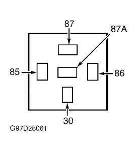
BLOWER MOTOR DOES NOT OPERATE 1. Check Fuse Turn ignition off. Check WIPER fuse (20-amp) located in instrument panel fuse panel. Check BLOWER circuit breaker (30-amp) located in instrument panel fuse panel. If fuse and circuit breaker are okay, go to step 5). If WIPER fuse is blown, go to next step. If BLOWER circuit breaker is bad, go to step 3). 2. Check Circuit For Short To Ground Replace WIPER fuse (20-amp). Disconnect blower motor relay located in instrument panel fuse panel. Turn ignition on. Recheck WIPER fuse. If fuse is okay, reinstall relay and to step 5). If fuse is blown, repair short to ground in Blue wire between fuse and relay. 3. Check Circuit For Short To Ground Turn ignition off. Disconnect blower motor relay located in instrument panel fuse panel. Reset HEATER circuit breaker. If circuit breaker is okay, go to next step. If circuit breaker blows again, repair short to ground in Blue/Orange wire between circuit breaker and relay. 4. Check Circuit For Short To Ground Turn ignition off. Disconnect blower motor connector. Measure resistance between ground and blower motor relay connector terminal No. 87 (Blue/White wire). See Fig. 4 . If resistance is greater than 10 k/ohms, replace blower motor relay. If resistance is not greater than 10 k/ohms, repair short to ground in Blue/White wire. 5. Check Voltage To Blower Motor Relay Turn ignition off. Disconnect blower motor relay. Turn ignition on. Measure voltage between ground and blower motor relay connector terminal No. 30 (Blue/Orange wire). See Fig. 4 . If voltage is greater than 10 volts, go to next step. If voltage is not greater than 10 volts, Repair open in Blue/Orange wire between relay and HEATER circuit breaker. 6. Check Voltage To Coil Side Of Blower Motor Relay Measure voltage between ground and blower motor relay connector terminal No. 85 (Blue wire). See Fig. 4 . If voltage is greater than 10 volts, go to next step. If voltage is not greater than 10 volts, repair open in Blue wire between relay connector and WIPER fuse. 7. Check Blower Motor Relay Ground Measure resistance between ground and blower motor relay connector terminal No. 86 (Black wire). See Fig. 4 . If resistance is less than 5 ohms, reconnect relay and go to next step. If resistance is not less than 5 ohms. repair open in Black wire between relay and ground. 8. Check Voltage To Blower Motor Turn ignition off. Disconnect blower motor connector. Turn ignition on. Measure voltage between Page 1 of 3 A/C ground and blower motor harness connector Blue/White wire. If voltage is greater than 10 volts, go to step 10). If voltage is not greater than 10 volts, go to next step.
Check Circuit Continuity Turn ignition off. Disconnect blower motor relay. Measure resistance between blower motor relay connector terminal No. 87 (Blue/White wire) and blower motor harness connector Blue/White wire. See Fig. 4 . If resistance is less than 5 ohms, replace blower motor relay. If resistance is not less than 5 ohms, repair Blue/White wire between blower motor relay connector and blower motor harness connector. Fig. 4: Blower Motor Relay Connector Terminals Courtesy of FORD MOTOR CO.
Check Voltage To Blower Motor Resistor Turn ignition off. Disconnect blower motor resistor 1-pin connector (Blue/Black wire). Turn ignition on. Measure voltage between ground and blower motor resistor 1-pin connector (Blue/Black wire). If voltage is greater than 10 volts, reconnect blower motor resistor connector and go to next step. If voltage is not greater than 10 volts, replace blower motor assembly. See BLOWER MOTOR under REMOVAL & INSTALLATION.
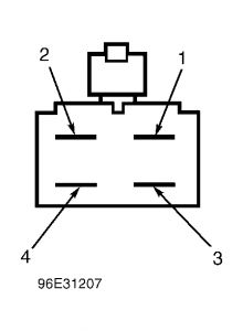
Check Voltage From Blower Motor Resistor Turn ignition off. Disconnect blower motor resistor 4-pin connector. Turn ignition on. Measure voltage between ground and blower motor resistor terminal No. 4. See Fig. 5 . If voltage is greater than 10 volts, go to next step. If voltage is not greater than 10 volts, replace blower motor resistor. See BLOWER RESISTOR under REMOVAL & INSTALLATION. Fig. 5: Blower Motor Resistor Terminals Courtesy of FORD MOTOR CO.
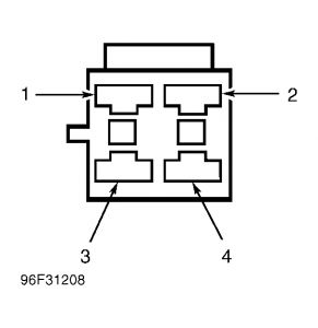
Check Circuit Continuity Turn ignition off. Disconnect function selector switch connector. Measure resistance between blower motor resistor harness connector terminal No. 4 (Blue/Yellow wire) and function selector switch harness connector terminal No. 4 (Blue/Yellow wire). See Fig. 2 and Fig. 6 . If resistance is less than 5 ohms, go to next step. If resistance is not less than 5 ohms, repair Blue/Yellow wire between blower motor resistor connector and function selector switch connector. Fig. 6: Blower Motor Resistor Harness Connector Terminals Courtesy of FORD MOTOR CO.
Check Function Selector Switch Ground Measure resistance between ground and function selector switch harness connector terminal No. 3 (Black wire). See Fig. 2 . If resistance is less than 5 ohms, replace function selector switch. See CONTROL PANEL & SWITCHES under REMOVAL & INSTALLATION. If resistance is not less than 5 ohms, repair open in Black wire between function selector switch harness connector and ground.
Sep 6, 2008 at 5:48 AM