2004 Ford E-Series Van Electrical system not working

Tiny
WINDONTHERUNWAY
  • MEMBER
  • 2004 FORD E-SERIES VAN
  • V8
  • 2WD
  • AUTOMATIC
  • 90,000 MILES
Hi guys,

I have a 15 Passenger for van (for my band) and there's a major problem with the electrical system. A couple weeks ago everything flash off and then on while I was driving, then no issue for a couple weeks. Then on our way to a show everything turned off and stayed off for couple hours. On the way back, mid trip it all turned back on. We weren't "doing" anything but driving when this happened. Now everyhting is off and it seams like they are off for good.

I took it too a mechanic who I don't entirely trust and after working on it for two days he said it needs a new wiring harness. I know a lot about electricity and soldering. It seams to me like one loose wire but he wanted $1100 to fix which I cannot afford.


Currently the following DO NOT hasve power:
Stereo
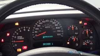
All Gauges (Gas, Speedometer, Tach, etc)
Mileage/Trip counter
Vanity Mirror Lights
Interior (overhead) lights
Auto Windows
Auto Mirrors
Birghts


The following have power and are working fine:
Regular headlights
Dash lights (gauges light up)
Power Locks
Wipers
Cigarette Lighter
Emergency blinkers
Overdrive switch light
AC/Heat
Wiper fluid

Any ideas what the issue could be? Can I fix this myself? THANK YOU SO MUCH FOR YOUR HELP!
Friday, April 9th, 2010 AT 2:55 PM

14 Replies

Tiny
KHLOW2008
  • MECHANIC
  • 41,815 POSTS
Hi windontherunway,

Thank you for the donation.

Seems a power supply is missing somewhere and I believe we can work this out without sending it to the mechanics.

In our data base we have many different categories for this vehicle so I need to make sure I get the vehicle correct.

The VIn would help.
What is the engine code?
You mentioned E-series, is it E150, E250 etc?
Was this
answer
helpful?
Yes
No
+1
Sunday, April 11th, 2010 AT 7:00 AM
Tiny
WINDONTHERUNWAY
  • MEMBER
  • 7 POSTS
The VIN is FBSS3IL94HB20520
not sure what the engine code is.
It's a E350 super duty 15 passenger van.

Thanks!
Was this
answer
helpful?
Yes
No
+1
Sunday, April 11th, 2010 AT 12:00 PM
Tiny
KHLOW2008
  • MECHANIC
  • 41,815 POSTS
I have sent out the power distribution wiring diagrams. Check your email and let me know if they come out correct.

From the wiring diagram, you should be able to trace and find out where the power supply is cut off.

Let me know what you find.
Was this
answer
helpful?
Yes
No
+1
Sunday, April 11th, 2010 AT 2:12 PM
Tiny
WINDONTHERUNWAY
  • MEMBER
  • 7 POSTS
Thanks a bunch!

I don't really know what to do with these now though. I can read them, but what and how should I test it? I have a multi meter.
Was this
answer
helpful?
Yes
No
Sunday, April 11th, 2010 AT 5:29 PM
Tiny
KHLOW2008
  • MECHANIC
  • 41,815 POSTS
Print them out and locate the items that are not working in the list. Trace back to where the fuses are and check them.
If fuses are good, test them for voltage with the multi-tester to confirm votltage is available.

If power is not available at the fuses, trace further back to where the main fuses are and test them.
Was this
answer
helpful?
Yes
No
Monday, April 12th, 2010 AT 6:57 AM
Tiny
WINDONTHERUNWAY
  • MEMBER
  • 7 POSTS
Ok the fuses are good and all have voltage. What's next?
Was this
answer
helpful?
Yes
No
+1
Tuesday, April 13th, 2010 AT 3:21 PM
Tiny
KHLOW2008
  • MECHANIC
  • 41,815 POSTS
Note the color of the wire for the circuits that you are looking at. From the fuse box, check for continuity between the fuses to the next connecting point such as connectors between the engine and body harness. If continuity is not present, check the circuit for breaks or damage to the wires. If continuity is good, check the next stage, going from the connector to the components.

From your sypmtom description, if the fuses are intact, the most likely cause would be loose, contaminated or overheated connectors.
Was this
answer
helpful?
Yes
No
Tuesday, April 13th, 2010 AT 3:44 PM
Tiny
WINDONTHERUNWAY
  • MEMBER
  • 7 POSTS
I'm sorry: the last post was wrong. After I posted that I called my dad (who's a hobbyist certified plane mechanic) and he walked me through the wiring diagram and testing.

None of the fuses are burnt out, but a bunch don't have current (I was testing them wrong).

So we spend a couple hours (with my dad on the phone) and isolated the issue.

He says:

"There is a open circuit in our around the instrument cluster."

He thinks the instrument panel isn't ground correctly anymore.
We took a wire and grounded port 85 in the Accessory Delay Relay and the CD player came on as well as the windows.

What do you think the next step is? He said I should trace the Lt Blue/Red wire but it disappear WAY up in behind the steering column.

Thanks for your help!
Was this
answer
helpful?
Yes
No
Tuesday, April 13th, 2010 AT 7:10 PM
Tiny
KHLOW2008
  • MECHANIC
  • 41,815 POSTS
The Lt Blue/Red wire goes into the instrument cluster and is connected to the GEM Module which controls the Accessory Delay Relay.

It could be a faulty meter cluster or the GEM and I have sent the instrument cluster schematic to you.

The ground circuit for the instrument cluster is at left side of dash and left kick panel, check for loose or contaminated grounds. Remove and clean to be sure it is good.

I can't seem to find any other information on the GEM so you would have to hold on while I try to get it and maybe get some assistance from other technicians.
Was this
answer
helpful?
Yes
No
Wednesday, April 14th, 2010 AT 7:04 AM
Tiny
MERLIN2021
  • MECHANIC
  • 17,250 POSTS
Could be the GEM, or the cluster itself, try this dealer test mode, write down any and all codes displayed.
INSTRUMENT CLUSTER DEALER TEST MODE
To enter the Instrument Cluster Dealer Test Mode, press and hold the instrument cluster
SELECT/RESET button and then turn the ignition switch to the RUN position. Continue pressing the
SELECT/RESET button (five seconds) until test is displayed in the odometer. The SELECT/RESET
button must be released within three seconds of the odometer displaying TEST to begin the dealer
test mode. Depress the SELECT/RESET button to advance through the following steps until DTC is
displayed. Depressing the SELECT/RESET button will display any continuous DTCs stored before
proceeding to the next step.


https://www.2carpros.com/forum/automotive_pictures/62217_1_80.jpg


https://www.2carpros.com/forum/automotive_pictures/62217_2_63.jpg


https://www.2carpros.com/forum/automotive_pictures/62217_3_47.jpg


https://www.2carpros.com/forum/automotive_pictures/62217_4_22.jpg

Was this
answer
helpful?
Yes
No
-1
Wednesday, April 14th, 2010 AT 4:13 PM
Tiny
WINDONTHERUNWAY
  • MEMBER
  • 7 POSTS
The Dealer mode test didn't work: the odometer doesn't have power so nothing even lights up.

I'm ready to jump into the instrument cluster. But it and the wires are totally covered. Do I need to remove the entire dash? Also can you give more specific instructions for checking the ground wire for it? Like I said there are a ton of wires back there. Thanks for your help.
Was this
answer
helpful?
Yes
No
+1
Saturday, April 17th, 2010 AT 12:16 PM
Tiny
MERLIN2021
  • MECHANIC
  • 17,250 POSTS
I would remove the cluster, then unplug the connectors, check the pins on the cluster, see if any are loose or spin, re-solder any of these then check for pushed out pins in the connectors. The other option is a trip to Ford for a scan. It needs the "B" and "U" codes read, this requires a special scan tool.
Was this
answer
helpful?
Yes
No
Saturday, April 17th, 2010 AT 12:28 PM
Tiny
WINDONTHERUNWAY
  • MEMBER
  • 7 POSTS
How do I remove it? Do I have to remove the dash? Are there any instructions for doing so?
Was this
answer
helpful?
Yes
No
Saturday, April 17th, 2010 AT 12:33 PM
Tiny
MERLIN2021
  • MECHANIC
  • 17,250 POSTS
Cluster needs to be scanned and after the new one goes in, it needs this info downloaded to it. That requires a Ford scan tool. Just checking yours should be OK to. Emailed the file with the how to!
Was this
answer
helpful?
Yes
No
+1
Saturday, April 17th, 2010 AT 4:41 PM

Please login or register to post a reply.

Sponsored links