Welcome back and you are very welcome. On your vehicle, the sensor is one in the same. The bad part is (and I'm basing this on the 3.5L V6 engine), the sensor is located under the intake manifold and requires removal of the intake to access it. It makes a five minute job take hours.
Before you get started on this, you may want to contact the local Ford Dealership. This vehicle has a 7 year/70,000 mile emissions warranty on many of the parts. Considering a coolant temperature sensor will change the emissions emitted into the atmosphere, it should be covered under the warranty. Also, you don't have to be the first owner for this to apply.
To replace the sensor, you first have to remove the upper and then lower intake manifolds. I will provide the directions in the order you need to do them. They will be in this order:
1) Upper intake removal
2) Lower Intake removal
3) Coolant temp sensor
All attached pictures will correlate with these directions.
____________________________________________________________________
Upper intake, the first 12 pics correlate with this process.
Upper Intake Manifold
Removal
NOTICE: If the engine is repaired or replaced because of upper engine failure, typically including valve or piston damage, check the intake manifold for metal debris. If metal debris is found, install a new intake manifold. Failure to follow these instructions can result in engine damage.
1. Remove the ACL (Air Cleaner) outlet pipe. Refer to Intake Air System Components - Exploded View See: Air Cleaner Housing > Removal and Replacement > Intake Air System Components - Exploded View.
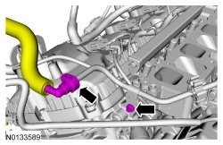
2. Disconnect the EVAP (Evaporative Emission) canister purge valve and throttle body electrical connectors.
- Detach the wiring harness pin-type retainer.
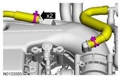
3. Disconnect the EVAP (Evaporative Emission) vapor tube from the EVAP (Evaporative Emission) canister purge valve. REFER to Section 310-00, Quick Connect Coupling See: Fuel Line Coupler > Removal and Replacement > Quick Connect Coupling.
- Detach the EVAP (Evaporative Emission) vapor tube from the 2 retainers.
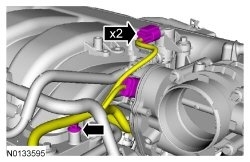
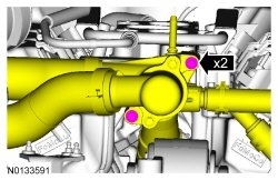
4. Release the clamps and disconnect the power brake booster vacuum supply hose and crankcase ventilation hose from the upper intake manifold.
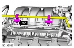
5. Detach the 2 coolant tube retainers from the upper intake manifold.
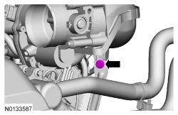
6. Remove the upper intake manifold support bracket bolt.
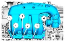
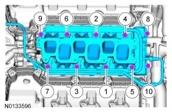
7. Remove the 7 bolts and the upper intake manifold.
- Remove and discard the gasket.
- Clean and inspect all of the sealing surfaces of the upper and lower intake manifold.
Installation
1. Using a new gasket, install the intake manifold and the 7 bolts and tighten in the sequence shown in 2 stages.
- Stage 1: Tighten to 10 Nm (89 lb-in).
- Stage 2: Tighten an additional 45 degrees.
2. Install the upper intake manifold support bolt.
- Tighten to 10 Nm (89 lb-in).
3. Attach the 2 coolant tube retainers to the upper intake manifold.
4. Connect the power brake booster vacuum supply hose and crankcase ventilation hose to the upper intake manifold.
5. Connect the EVAP (Evaporative Emission) vapor tube to the EVAP (Evaporative Emission) canister purge valve. REFER to Section 310-00, Quick Connect Coupling See: Fuel Line Coupler > Removal and Replacement > Quick Connect Coupling.
- Attach the EVAP (Evaporative Emission) vapor tube to the 2 retainers.
6. Connect the EVAP (Evaporative Emission) canister purge valve and throttle body electrical connectors.
- Attach the wiring harness pin-type retainer to the upper intake manifold.
7. Install the ACL (Air Cleaner) outlet pipe. Refer to Intake Air System Components - Exploded View See: Air Cleaner Housing > Removal and Replacement > Intake Air System Components - Exploded View.
____________________
Lower Intake Manifold Start at picture 13
LOWER INTAKE MANIFOLD
Lower Intake Manifold
Removal
NOTICE: During engine repair procedures, cleanliness is extremely important. Any foreign material, including any material created while cleaning gasket surfaces that enters the oil passages, coolant passages or the oil pan, can cause engine failure.
1. With the vehicle in NEUTRAL, position it on a hoist. REFER to Section 100-02, Jacking and Lifting See: Vehicle Lifting > Procedures > Jacking and Lifting, Lifting Points.
2. Release the fuel system pressure. REFER to Section 310-00, Fuel System Pressure Release See: Fuel Pressure Release > Procedures > Fuel System Pressure Release.
3. Disconnect the battery ground cable. Refer to Battery Disconnect See: Battery > Removal and Replacement > Battery Disconnect.
4. Drain the cooling system. Refer to Cooling System Draining, Filling and Bleeding See: Cooling System > Procedures > Cooling System Draining, Filling and Bleeding.
5. Remove the upper intake manifold. Refer to Upper Intake Manifold See: Intake Manifold > Removal and Replacement > Upper Intake Manifold.
6. Disconnect the 6 fuel injector electrical connectors.
7. Disconnect the fuel supply tube-to-fuel rail quick connect coupling. REFER to Section 310-00, Quick Connect Coupling See: Fuel Line Coupler > Removal and Replacement > Quick Connect Coupling. Position fuel supply tube aside.
- Remove the bolt from the fuel supply tube-to-rail bracket.
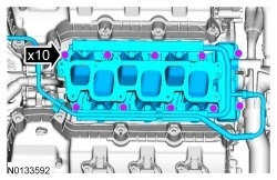
8. Remove the 2 thermostat housing-to-lower intake manifold bolts.
9. Remove the 10 bolts and the lower intake manifold.
- Remove and discard the intake manifold and thermostat housing gaskets.
- Clean and inspect all sealing surfaces.
Installation
1. NOTICE: If the engine is repaired or replaced because of upper engine failure, typically including valve or piston damage, check the intake manifold for metal debris. If metal debris is found, install a new intake manifold. Failure to follow these instructions can result in engine damage.
Using new intake manifold and thermostat housing gaskets, install the lower intake manifold and the 10 bolts.
- Tighten in the sequence shown to 10 Nm (89 lb-in).
2. Install the 2 thermostat housing-to-lower intake manifold bolts.
- Tighten to 10 Nm (89 lb-in).
3. Connect the fuel supply tube-to-fuel rail quick connect coupling. REFER to Section 310-00, Quick Connect Coupling See: Fuel Line Coupler > Removal and Replacement > Quick Connect Coupling.
- Install the bolt to the fuel supply tube-to-rail bracket and tighten to 10 Nm (89 lb-in).
4. Connect the 6 fuel injector electrical connectors.
5. Install the upper intake manifold. Refer to Upper Intake Manifold See: Intake Manifold > Removal and Replacement > Upper Intake Manifold.
6. Connect the battery ground cable. Refer to Battery Disconnect See: Battery > Removal and Replacement > Battery Disconnect.
7. Fill and bleed the cooling system. Refer to Cooling System Draining, Filling and Bleeding See: Cooling System > Procedures > Cooling System Draining, Filling and Bleeding.
_____________________________
Finally, here are the directions for replacing the sensor. The last two pictures correlate with these directions.
____________________________
Cylinder Head Temperature (CHT) Sensor - 3.5L Ti-VCT, 3.7L Ti-VCT
Exploded View
Removal
WARNING: Before beginning any service procedure, refer to Safety Warnings. Failure to follow this instruction may result in serious personal injury.
1. Remove the lower intake manifold. For 3.5L Twin Independent Variable Cam Timing (Ti-VCT) engine, See: Intake Manifold > Removal and Replacement > Lower Intake Manifold.
2. Disconnect the CHT (Cylinder Head Temperature) sensor electrical connector.
3. Remove and discard the CHT (Cylinder Head Temperature) sensor.
Installation
1. NOTE: Do not reuse the CHT (Cylinder Head Temperature) sensor. Install a new sensor.
Install a new CHT (Cylinder Head Temperature) sensor.
- Tighten to 10 Nm (89 lb-in).
2. Connect the CHT (Cylinder Head Temperature) sensor electrical connector.
3. Install the lower intake manifold. For 3.5L Twin Independent Variable Cam Timing (Ti-VCT) engine, See: Intake Manifold > Removal and Replacement > Lower Intake Manifold.
___________________
As you can see, it's a big job. Please feel free to let me know if you have questions or need help with anything.
Take care,
Joe
Images (Click to make bigger)
Friday, December 28th, 2018 AT 10:19 PM