Hi COMERCIALAUTOSERVICE,
Thank you for the donation.
Here are the diagnostic procedures.
DTC P1391 : INTERMITTENT LOSS OF CMP OR CKP
NOTE: DTC P1391 : INTERMITTENT LOSS OF CMP OR CKP is monitored with engine running or cranking. DTC may be stored in Powertrain Control Module (PCM) when PCM senses FAILURE COUNTER reaches 96 failures for 2 consecutive trips. Possible causes are:
Crankshaft Position (CKP) sensor improperly installed, defective CKP sensor, defective distributor, defective Camshaft Position (CMP) sensor, defective PCM, defective flywheel, defective connectors or defective wiring.
1 . If vehicle is not equipped with a distributor, go to next step. Start engine and allow it to idle.
Using scan tool in set sync mode, check distributor position. If scan tool displays IN RANGE, go to next step. If scan tool does not display IN RANGE, loosen distributor hold-down clamp bolt and rotate distributor until reading is as close to zero degrees as possible and IN RANGE message is displayed. Tighten hold-down clamp bolt. Perform TEST VER-5A.
NOTE: CMP or CKP sensor signal loss can be detected by an RPM change, DTC or by observing oscilloscope pattern.
2 . Turn ignition off. To diagnose CMP or CKP sensor signal loss using oscilloscope, go to next step. To diagnose CMP or CKP sensor signal loss without using oscilloscope, go to step 16).
NOTE: Refer to manufacturer's operation manual for instructions in use of oscilloscope and procedure for pattern analysis.
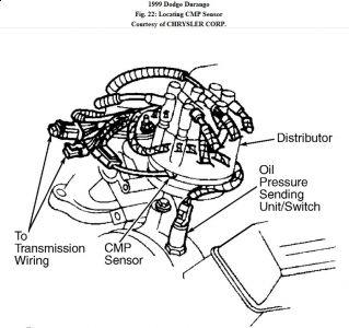
3 . Turn ignition off. Ensure CMP sensor connector is connected. For CMP sensor location, see
Fig. 22 . Using oscilloscope's voltage lead, backprobe CMP sensor connector, signal circuit (Tan/Yellow wire). Start engine and allow it to idle. If CMP sensor signal pattern is consistent, go to step 8 ). If CMP sensor signal pattern is not consistent, go to next step.
4 . Turn engine off. Disconnect CMP sensor connector. Visually inspect connector for corroded, damaged, pushed-out or miswired terminals. Repair connector as necessary. Perform TEST VER- 5A. If connector is okay, go to next step.
5 . Ensure ignition is off. Disconnect PCM Black connector. PCM is located in engine compartment. Visually inspect connector for corroded, damaged, pushed- out or miswired terminals. Repair connector as necessary. Perform TEST VER- 5A. If connector is okay, go to next step.
6 . Ensure ignition is off. Remove distributor cap. Inspect distributor rotor and drive for looseness. Repair distributor rotor or drive looseness as necessary. Perform TEST VER- 5A. If distributor rotor and drive are okay, go to next step.
7 . At this time, CMP sensor is assumed to be defective. Replace CMP sensor. Perform TEST
VER- 5A.
NOTE: Refer to manufacturer's operation manual for instructions in use of oscilloscope and procedure for pattern analysis.
8 . Ensure ignition is off. Ensure CMP sensor connector is still connected. Using oscilloscope's
voltage lead, backprobe PCM connector, CMP sensor signal circuit (Tan/Yellow wire). While monitoring oscilloscope pattern, wiggle CMP sensor signal circuit
from CMP sensor to PCM. If CMP sensor signal pattern is consistent, go to next step. If CMP sensor signal pattern is not consistent, repair wiring harness where wiggling caused oscilloscope pattern to become inconsistent. Perform TEST VER- 5A.
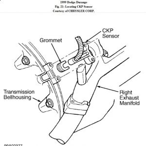
9 . Ensure ignition is off. Ensure CKP sensor connector is still connected. For CKP sensor location, see Fig. 21 . Using oscilloscope's voltage lead, backprobe CKP sensor connector, signal circuit (Gray/Black wire). Start engine and allow it to idle. If CKP sensor signal pattern is consistent, go to step 15). If CKP sensor signal pattern is not consistent, go to next step.
10. Ensure ignition is off. Disconnect CKP sensor connector. Visually inspect connector for
corroded, damaged, pushed-out or miswired terminals. Repair connector as necessary.
Perform TEST VER- 5A. If connector is okay, go to next step.
11 . Ensure ignition is off. Disconnect PCM Black connector. PCM is located in engine
compartment. Visually inspect connector for corroded, damaged, pushed- out or miswired terminals. Repair connector as necessary. Perform TEST VER- 5A. If connector is okay, go to next step.
12 . Inspect CKP sensor for proper installation. Correct CKP sensor installation as necessary.
Perform TEST VER- 5A. If CKP sensor is properly installed, go to next step.
13 . Ensure ignition is off. Remove CKP sensor. Inspect flywheel for damage or misalignment.
Repair flywheel as necessary. Perform TEST VER- 5A. If flywheel is okay, go to next step.
14 . At this time, CKP sensor is assumed to be defective. Replace CKP sensor. Perform TEST
VER- 5A.
15 . Turn ignition off. Using oscilloscope's voltage lead, backprobe PCM connector, CKP sensor
signal circuit (Gray/Black wire). Start engine and allow it to idle. While monitoring oscilloscope pattern, wiggle wiring harness from CKP sensor to PCM. If CKP
sensor signal pattern does not remain consistent while wiggling wiring harness, repair wiring harness where wiggling caused CKP sensor signal pattern to become inconsistent. Perform TEST VER- 5A. If CKP sensor signal pattern remains consistent while wiggling
wiring harness, test is complete.
16 . Turn engine off. Disconnect CKP sensor connector. For CKP sensor location, see Fig. 21 .
Visually inspect connector for corroded, damaged, pushed- out or miswired terminals. Repair connector as necessary. Perform TEST VER- 5A. If connector is okay, go to next step.
17 . Turn engine off. Disconnect CMP sensor connector. For CMP sensor location, see Fig. 22 .
Visually inspect connector for corroded, damaged, pushed- out or miswired terminals. Repair connector as necessary. Perform TEST VER- 5A. If connector is okay, go to next step.
18 . Ensure ignition is off. Disconnect PCM Black connector. Visually inspect connector for corroded, damaged, pushed- out or miswired terminals. Repair
connector as necessary. Perform TEST VER- 5A. If connector is okay, go to next step.
19 . Start engine and allow it to idle. Using scan tool, monitor engine RPM while wiggling CMP and CKP sensor wiring harness. If engine RPM changes while wiggling wiring harness, repair wiring harness where wiggling caused engine RPM change. Perform TEST VER- 5A. If RPM does not change, go to next step.
20 . At this time, conditions required to set DTC are present. Possible causes are: open or shorted 5 -volt supply circuit, open sensor ground, open or shorted signal circuit, excessive
CKP or CMP sensor clearance, damaged CKP or CMP sensor, defective CKP sensor, defective CMP sensor or defective PCM. See INACTIVE DTC CONDITION. Test is complete.
Aug 27, 2009 at 11:26 AM
