1997 Dodge Dakota Altenator not charging battery

Tiny
TALCOL1
  • MEMBER
  • 1997 DODGE DAKOTA
Electrical problem
1997 Dodge Dakota V8 Four Wheel Drive Automatic

I have had the altenator bench tested and tried a new altenator, I had the battery tested (checked good) and still can not get the altenator to charge the battery. I have replaced the PCM twice. When I put the 1st new PCM in the battery charged at 13.57 for about 5 minutes and then dropped to 11.97 and declined. I had a repair shop check the charging system and put the second new PCM. They drove it and I checked it at the shop and it was charging at 13.75. I thought I had the problem fixed. I drove 35 miles home and all seemed fine. Went to drive the truck to the store and same old problem was back. The system is only chraging at 11.87. The repair shop does not have a clue as to what is happening. What could be burning out these PCM, s. HELP!
Tuesday, June 29th, 2010 AT 9:50 PM

12 Replies

Tiny
BMRFIXIT
  • MECHANIC
  • 19,053 POSTS
Don't suspect PCM 1st
wiring issue most likely check connector at the PCM plug


https://www.2carpros.com/forum/automotive_pictures/99387_Graphic_91.jpg


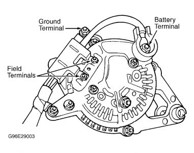
Using an external voltmeter, connect one voltmeter lead to B+ (battery) terminal on rear of generator. Connect other voltmeter lead to positive battery terminal. Go to next step.
Start engine and note voltage reading on voltmeter. If voltage is more than 0.4 volt, repair B+ circuit between battery and generator for high resistance If voltage is 0.4 volt or less, go to next step.
Turn ignition off. Using external voltmeter, connect one voltmeter lead to generator case. Connect other voltmeter lead to negative battery terminal. Go to next step.
Start engine and allow to reach operating temperature. Note voltage reading on voltmeter. If voltage is more than 0.1 volt, repair generator ground circuit between battery and generator for high resistance If voltage is 0.1 volt or less, go to next step.
Maintain engine speed at 1600 RPM. Using scan tool, read target charging voltage and charging voltage. Compare readings. If difference between readings is more than one volt, repair or replace generator as necessary . If difference between readings is one volt or less, go to next step.
Allow engine to idle. Turn ignition off. Perform TEST CH-1A - CHARGING SYSTEM NO CODE TEST.

TEST CH-1A - CHARGING SYSTEM NO CODE TEST
NOTE:Perform DTC TEST , Ensure battery is fully charged before proceeding.

Inspect generator belt for proper tension and good condition. If generator belt is okay, go to next step. If generator belt tension is incorrect or belt is damaged, repair as necessary.
Start engine. Using scan tool, set engine speed at 2000 RPM for 30 seconds. Using scan tool, return engine speed to idle and read Diagnostic Trouble Codes (DTCs). If any DTCs pertaining to charging system exist, go to appropriate test. .
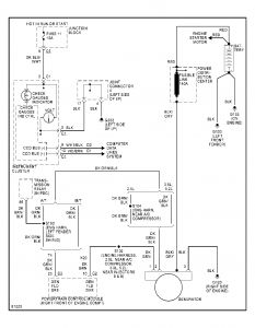
Turn ignition off. Turn ignition on with engine off. Using scan tool, actuate generator field. Using scan tool in voltmeter mode, backprobe Dark Green wire at 2-wire connector on rear of generator. Voltage should cycle from zero volts to battery voltage every 1.4 seconds.
While monitoring voltage display on scan tool, wiggle wiring from 2-pin connector on rear of generator to Powertrain Control Module (PCM). PCM is located between driver's side front fender and power distribution center, near battery.
If no interruption of normal voltage cycle exists when wiggling wiring, go to next step. If interruption of normal voltage cycle exists when wiggling wiring, repair wiring as necessary.

Using scan tool, read DTCs. If any DTCs exist pertaining to charging system, go to appropriate test.
Using external voltmeter, connect voltmeter positive lead on B+ (battery) terminal on rear of generator. Connect voltmeter negative lead to positive battery terminal.
Start engine and note voltage reading on voltmeter. If voltage is 0.4 volt or less, go to next step. If voltage is more than 0.4 volt, repair B+ circuit between battery and generator for high resistance.
Turn ignition off. Using external voltmeter, connect voltmeter positive lead on generator case. Connect voltmeter negative lead to negative battery terminal.
Start engine and note voltage reading on voltmeter. If voltage is 0.1 volt or less, go to next step. If voltage is more than 0.1 volt, repair generator ground circuit from generator case to negative battery terminal for high resistance.
Remove external voltmeter. Using scan tool, read and record battery voltage reading. Using external voltmeter, read and record battery voltage between positive and negative battery terminals.
Compare both voltage readings obtained in step 11). If difference between both voltage readings is less than one volt, test is complete. If difference between both voltage readings is one volt or more, go to next step.
Turn ignition off. Disconnect PCM connectors. Using external voltmeter, check voltage between ground and terminal No. 22 (Red/Black wire) at PCM Black connector. Compare voltage reading to voltage reading obtained using scan tool in step 11).
If voltage reading is not within one volt of voltage reading obtained using scan tool in step 11), replace PCM
If voltage reading is within one volt of voltage reading obtained using scan tool in step 11), repair high resistance on Red/White wire between PCM Black connector terminal No. 22 and battery.
Was this
answer
helpful?
Yes
No
-1
Tuesday, June 29th, 2010 AT 10:34 PM
Tiny
TALCOL1
  • MEMBER
  • 7 POSTS
I have completed all checks, although I do not have a scan tool the machanic that worked on my truck said he ran all scan checks. I traced Red/white wire and found everything fine. Today I tried to do an external voltage regulator with no improvement. I connected the external voltage regulator as discribed on the internet (both field terminal wires connected to each prong on the external voltage regulator and a 12v wire connected to the the top prong with one of the field wires also mounted it to the firewall for ground). The only time I have been able to get the altenator to charge is by replacing the PCM (like I said twice), however it seems like something is burning out the PCM's after a short while.
Was this
answer
helpful?
Yes
No
Wednesday, June 30th, 2010 AT 5:09 PM
Tiny
BMRFIXIT
  • MECHANIC
  • 19,053 POSTS
What would burn an PCM is a short and or internal failure

1st try and check for codes
no scanner ! No problem try this to retrive codes

Ensure battery is fully charged.
Turn ignition on and note operation of MIL.
When ignition is first turned on, MIL should come on and remain on for 3 seconds to verify bulb and circuit operation, and then go off.
Turn ignition on-off-on-off-on within 5 seconds.

Record 2-digit DTCs displayed by MIL flashing on and off. (Flash----flash-flash is code 12 and so on )

i will look more into it for you

try this mean while and let me know if any changes
disconnect battery and unplug the PCM
wait a min and reconnect PCM and then battery start and check
Was this
answer
helpful?
Yes
No
Wednesday, June 30th, 2010 AT 5:27 PM
Tiny
TALCOL1
  • MEMBER
  • 7 POSTS
Thanks for the quick response. I checked for codes and did not see the MIL blink, however it did record a code 12 (which I think is battery disconnected with-in last 50 starts)
I did disconnect the battery and PCM. Reconnected both. No joy, still not charging. I'll wait for further info.
I'm pretty sure it would not be an internal failure because this is number 3 PCM and I don't think all three were internally bad.
Was this
answer
helpful?
Yes
No
Wednesday, June 30th, 2010 AT 6:45 PM
Tiny
TALCOL1
  • MEMBER
  • 7 POSTS
I must of missed this check the other day. A friend and I were rechecking things today and discovered that, we could not get the field wires to cycle every 1.4 seconds as discribed in your first posting. I don't know if we are doing it wrong or not. Touching the positive lead on the voltmeter to the green field wire and the negative lead to a ground we could only get a reading of 6.7 (with the ignition in the on position) and it would not change. We did this to both green wires with same result.
Was this
answer
helpful?
Yes
No
-1
Thursday, July 1st, 2010 AT 3:08 PM
Tiny
BMRFIXIT
  • MECHANIC
  • 19,053 POSTS
OPERATION
The amount of amperage produced by the generator is controlled by Electronic Voltage Regulator (EVR) circuitry within the PCM. EVR circuitry is connected in series with the generator field driver terminal and ground. A Battery Temperature Sensor (BTS), located in battery tray, is used to sense battery temperature. Sensed battery temperature and data from monitored line voltage is used by PCM to adjust battery charging rate. This is accomplished by cycling the ground path to control the strength of generator rotor magnetic field. PCM then compensates and regulates generator amperage output accordingly.

80% of the test depend on a scan tool to communicate and energize the field
And other than using an Ohm meter to check for short and or poor connection
most of the test is invalid


https://www.2carpros.com/forum/automotive_pictures/99387_Graphic_94.jpg

Was this
answer
helpful?
Yes
No
+2
Friday, July 2nd, 2010 AT 6:28 AM
Tiny
TALCOL1
  • MEMBER
  • 7 POSTS
I replaced the battery temp sensor tonight and still had the same problem. Battery still not charging! Please let me know if you have anymore suggestions?
Was this
answer
helpful?
Yes
No
-1
Sunday, July 4th, 2010 AT 11:04 PM
Tiny
BMRFIXIT
  • MECHANIC
  • 19,053 POSTS
Check email for wiring daigram
Was this
answer
helpful?
Yes
No
Monday, July 5th, 2010 AT 7:11 AM
Tiny
TALCOL1
  • MEMBER
  • 7 POSTS
Thanks for the wiring diagram. I will continue to shot wires. In the mean time, I got an external voltage regulator to work. I wired as I had seen on this website and NOW HAVE (woo hoo) the battery charging at 13.52 volts. Maybe you can tell me why the coil fuse blows anytime I tramp the gas pedal on the highway or in park in the driveway? I replaced the 10 amp fuse with a 30 amp and am able to drive it a normal speeds. But if I tramp the gas it will blow the fuse and shut the truck down. Putting another good fuse in gets me going again. I appreciate all the help you have provided.
Was this
answer
helpful?
Yes
No
Tuesday, July 6th, 2010 AT 9:41 PM
Tiny
BMRFIXIT
  • MECHANIC
  • 19,053 POSTS
Sorry not seen this before
continue with the wiring looking for a short
and check coil
coil is a very common failure
Was this
answer
helpful?
Yes
No
Tuesday, July 6th, 2010 AT 10:25 PM
Tiny
TALCOL1
  • MEMBER
  • 7 POSTS
Hey guys, I think I found my own coil fuse problem. I hooked up the 12v ignition wire for my external voltage regulator to the 12v ignition side of the Auto Shut Down relay. The auto shut down relay seems to be wired to the coil fuse somehow. I rewired it tonight to a different 12v ignition relay and I still have power to my external volatage regulator and I am not blowing the fuse now. I do still have the charging issue through the PCM! Thanks again and if I have future problems I will be back on this website! It rocks!
Was this
answer
helpful?
Yes
No
Wednesday, July 7th, 2010 AT 9:44 PM
Tiny
BMRFIXIT
  • MECHANIC
  • 19,053 POSTS
Thank you
Was this
answer
helpful?
Yes
No
+1
Thursday, July 8th, 2010 AT 6:02 AM

Please login or register to post a reply.

Sponsored links