Hi and thanks for using 2CarPros.
The compression is low. The manufacturer's specs are as follow:
Cylinder Compression Pressure
Cylinder Compression Pressure 1172 - 1551 kPa (170 - 225 psi)
Maximum Variation Between Cylinders 25 %
Recheck engine timing and let me know what you find. It sounds like you may have jumped time. One tooth off on the belt can be the issue. Here are the directions for belt replacement. I am providing it all because it shows all timing marks and repair information if needed. The attached pictures correlate with these directions.
___________________________________
TIMING BELT
REMOVAL
1. Disconnect negative battery cable.
2. Raise vehicle on hoist. Remove right front wheel.
3. Remove the right splash shield.
4. Remove accessory drive belts.
5. Remove crankshaft damper.
6. Remove the lower torque strut.
7. Disconnect exhaust system from manifold.
8. Disconnect A/C pressure switch at rear of compressor housing.
9. Lower vehicle and support engine with a jack.
10. Discharge A/C system and disconnect A/C lines at coupling block.
11. Remove upper torque strut.
12. Remove screw attaching ground to strut bracket.
13. Remove torque strut bracket.
14. Remove upper radiator support cross-member.
15. Remove power steering pump and bracket. Set pump aside. Do not disconnect lines from pump.
16. With engine properly supported, remove right engine mount through bolt.
17. Raise engine with jack until engine support bracket bolts are accessible.
Picture 1
18. Remove support bracket bolts (Fig. 81).
19. Remove support bracket (Fig. 81).
Picture 2
20. Remove upper timing belt cover fasteners and remove cover (Fig. 80).
21. Remove lower timing belt cover fasteners and remove cover (Fig. 80).
CAUTION: When aligning crankshaft and camshaft timing marks always rotate engine from crankshaft. Camshaft should not be rotated after timing belt is removed. Damage to valve components may occur. Always align timing marks before removing timing belt.
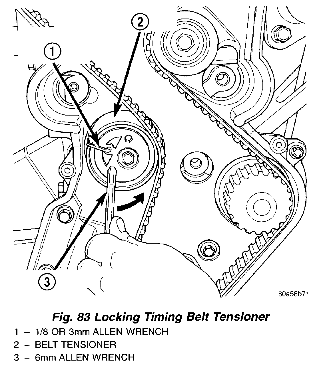
Picture 3
22. Before the removal of the timing belt, rotate crankshaft until the TDC mark on oil pump housing aligns with the TDC mark on crankshaft sprocket (trailing edge of sprocket tooth) (Fig. 82).
NOTE: The crankshaft sprocket TDC mark is located on the trailing edge of the sprocket tooth. Failure to align trailing edge of sprocket tooth to TDC mark on oil pump housing will cause the camshaft timing marks to be misaligned.
Picture 4
23. Install 6 mm Allen wrench into belt tensioner. Before rotating the tensioner, insert the long end of a 1/8" or 3 mm Allen wrench into the pin hole on the front of the tensioner (Fig. 83). While rotating the tensioner counterclockwise, push in lightly on the 1/8" or 3 mm Allen wrench, until it slides into the locking hole.
24. Remove timing belt.
CAUTION: If timing belt was damaged due to incorrect tracking (alignment), the belt tensioner assembly must be replaced.
INSTALLATION
1. Set crankshaft sprocket to TDC by aligning the sprocket with the arrow on the oil pump housing.
Picture 5
2. Set camshafts timing marks so that the exhaust camshaft sprocket is a 1/2 notch below the intake camshaft sprocket (Fig. 84).
CAUTION: Ensure that the arrows on both camshaft sprockets are facing up.
Picture 6
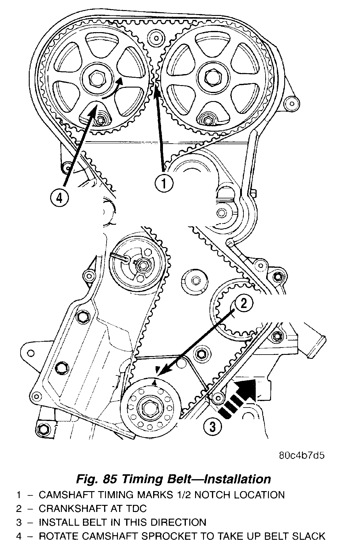
3. Install timing belt. Starting at the crankshaft, go around the water pump sprocket, idler pulley, camshaft sprockets and then around the tensioner (Fig. 85).
4. Move the exhaust camshaft sprocket counterclockwise (Fig. 85) to align marks and take up belt slack.
NOTE: A new tensioner is held in the wound position by a pull pin.
5. Remove the pull pin or Allen wrench from the belt tensioner.
Picture 7
6. Once the timing belt has been installed and tensioner released, rotate the crankshaft two (2) complete revolutions. Verify that the TDC marks on crankshaft and timing marks on the camshafts are aligned as shown in (Fig. 86).
7. Install lower timing belt cover and tighten fasteners to 4.5 Nm (40 in. Lbs.) (Fig. 80).
8. Install upper timing belt cover and tighten fasteners to 4.5 Nm (40 in. Lbs.) (Fig. 80).
9. Install right engine support bracket. Ensure the power steering pump is properly located in mounting location on bracket. Tighten mount bracket bolts to 61 Nm (45 ft. Lbs.) (Fig. 81).
10. Lower engine into mounting position and install right engine mount through bolt. Tighten bolt to 118 Nm (87 ft. Lbs.).
11. Install power steering pump and bracket.
12. Install upper radiator support crossmember.
13. Install torque strut bracket to strut tower.
14. Connect ground strap to bracket.
15. Install upper torque strut.
16. Connect A/C lines and charge A/C system.
17. Raise vehicle.
18. Connect exhaust system to manifold.
19. Connect A/C pressure switch connector.
20. Install crankshaft damper.
21. Install accessory drive belts.
22. Install lower torque strut.
23. Perform torque strut adjustment procedure.
24. Install right splash shield.
25. Install right front wheel.
26. Connect negative cable to battery.
27. Perform camshaft/crankshaft synchronization procedure. Refer to: Engine : Service and Repair : Engine Overhaul : See: Engine > Procedures > Camshaft/Crankshaft Synchronization
Let me know what you find. I have a feeling this is the problem.
Joe
Images (Click to make bigger)
SPONSORED LINKS
Tuesday, February 26th, 2019 AT 7:32 PM