Can you give me the code that was set so I can help narrow the area of failure and pinpoint your issue?
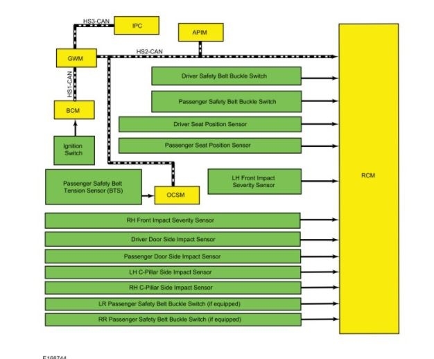
I attached the description of the system for you to view so you get a better understanding of how it works.
Roy
Supplemental Restraint System
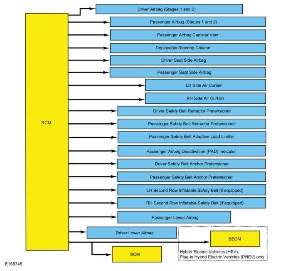
The SRS (supplemental restraint system) is controlled by the RCM (restraints control module), which continually monitors various inputs. When these inputs indicate a frontal or side crash, the RCM (restraints control module) may deploy some components, based upon the severity of the crash and the sensor inputs. To view the SRS (supplemental restraint system) inputs and outputs:
Refer to: Airbag and Seatbelt Pretensioner Supplemental Restraint System (SRS) - System Operation and Component Description See: Air Bag Systems > Components > Airbag and Seatbelt Pretensioner Supplemental Restraint System (SRS) - System Operation and Component Description.
Although some deployable devices may not have activated for all occupants during a crash, it does not mean that something is wrong with the SRS (supplemental restraint system).
The RCM (restraints control module) performs a self-test of the complete SRS (supplemental restraint system) during each startup. In addition to the self-test at start up, the RCM (restraints control module) continuously monitors all of its SRS (supplemental restraint system) components and circuitry for correct operation.
Airbag Warning Indicator
The airbag warning indicator:
- proves out by lighting for 6 seconds and then turning off.
- flashes and/or illuminates based on the message the IPC (instrument panel cluster) receives from the RCM (restraints control module).
- illuminates if the IPC (instrument panel cluster) does not receive a message from the RCM (restraints control module).
When the ignition is turned ON during normal operation, the IPC (instrument panel cluster) illuminates the airbag warning indicator continuously for 6 seconds. If the SRS (supplemental restraint system) is free of faults, the airbag warning indicator turns off and remains off. If a SRS (supplemental restraint system) fault exists, the airbag warning indicator illuminates and remains illuminated for the rest of the ignition cycle. The RCM (restraints control module) communicates with the IPC (instrument panel cluster) via the High Speed Controller Area Network 2 (HS2-CAN) and High Speed Controller Area Network 3 (HS3-CAN). The IPC (instrument panel cluster) illuminates the airbag warning indicator based on messaging from the RCM (restraints control module) (via the GWM (gateway module A). The IPC (instrument panel cluster) also illuminates the airbag warning indicator if there is no communication between the RCM (restraints control module) and IPC (instrument panel cluster).
Secondary Airbag Warning
A secondary airbag warning message is displayed and controlled by the IPC (instrument panel cluster). If the RCM (restraints control module) detects a SRS (supplemental restraint system) fault, the RCM (restraints control module) sends a message to the GWM (gateway module A), which sends it to the IPC (instrument panel cluster). The IPC (instrument panel cluster) then illuminates the airbag warning indicator. If the IPC (instrument panel cluster) detects a fault with the airbag warning indicator, a DTC (diagnostic trouble code) is stored in the IPC (instrument panel cluster) and a warning message is displayed in the message center to indicate that a SRS (supplemental restraint system) fault is present.
Event Notification Signal
The event notification feature provides other vehicle subsystems with information pertaining to SRS (supplemental restraint system) deployment or fuel cutoff status. When an impact occurs which exceeds a pre-determined threshold, the RCM (restraints control module) sends a signal on a dedicated circuit to the BCM (body control module). On Hybrid Electric Vehicles (HEVs) or Plug-in Hybrid Electric Vehicles (PHEVs), the BECM (battery energy control module) also receives this signal.
For all vehicles, when the BCM (body control module) receives the crash signal input, it initiates fuel cutoff to disable the fuel system.
For Hybrid Electric Vehicles (HEVs) and Plug-in Hybrid Electric Vehicles (PHEVs), the BECM (battery energy control module) commands the high voltage contactors open when the crash signal is received from the RCM (restraints control module).
After the fuel system is disabled, the vehicle can be re-started after carrying out the following steps:
- Turn the ignition OFF.
- Turn the ignition to START (on vehicles with push button start, press the start/stop button while the brake pedal is pressed).
- Turn the ignition OFF.
- Turn the ignition ON.
Occupant Classification System (OCS)
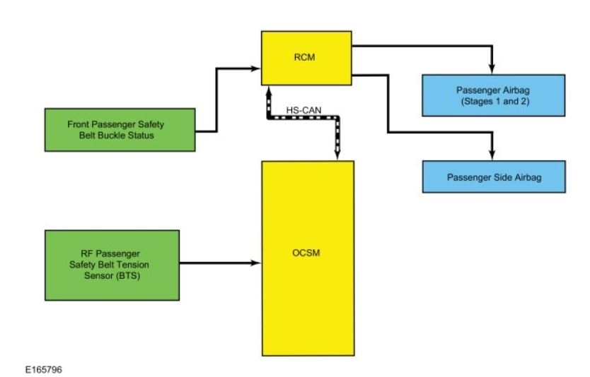
The OCS (occupant classification system) classifies the size of the front passenger seat occupant and provides this information to the RCM (restraints control module).
Pressure is applied to the OCS (occupant classification system) bladder when weight of any occupant or object in the front passenger seat is present. The pressure is then transferred through a tube and sensed by the OCS (occupant classification system) pressure sensor within the OCSM (occupant classification system module). The OCSM (occupant classification system module) sends information concerning the weight of any occupant or object on the front passenger seat to the RCM (restraints control module) via the High Speed Controller Area Network 2 (HS2-CAN). The RCM (restraints control module) uses this information when determining if the passenger airbag needs to be deployed in the event of a crash.
The OCS (occupant classification system) is also used for operation of the passenger Belt-Minder(R).
Refer to: Seatbelt Systems - System Operation and Component Description.
To deactivate or reactivate the passenger Belt-Minder(R) feature, Refer to: Seatbelt Minder Deactivating/Activating.
Passenger Airbag Deactivation (PAD) Indicator
The RCM (restraints control module) controls the PAD (passenger airbag deactivation) indicator through a direct, hardwired connection, based on information provided by the OCS (occupant classification system). The PAD (passenger airbag deactivation) indicator illuminates to indicate the passenger airbag is disabled. An exception to this is when the front passenger seat is determined to be empty and indication of a deactivated passenger airbag is not necessary. In all other cases, the PAD (passenger airbag deactivation) indicator is off when the passenger airbag is enabled.
The RCM (restraints control module) briefly activates the PAD (passenger airbag deactivation) indicator to prove out the indicator function and verify proper functional operation of the PAD (passenger airbag deactivation) indicator to the front occupants.
The following table indicates the passenger airbag and PAD (passenger airbag deactivation) indicator status based on the size of the front passenger occupant.
Image
Airbag Second Stage Deployment Check
The driver and passenger front airbags each have 2 deployment stages. After an airbag deployment, it is possible that stage 1 has deployed and stage 2 has not. If a front airbag has deployed, the front airbag must be remotely deployed using the appropriate airbag disposal procedure to make sure both stages have been deployed. For information on driver airbag and/or passenger airbag remote deployment:
Refer to: Pyrotechnic Device Disposal See: Restraints and Safety Systems > Procedures > Pyrotechnic Device Disposal.
SOS Post-Crash Alert System(TM)
The SOS Post-Crash Alert System(TM) is controlled by the BCM (body control module), but initiated by the RCM (restraints control module).
When a deployment event occurs, the RCM (restraints control module) sends a message on the HS-CAN (high speed-controller area network) to the BCM (body control module). The BCM (body control module) flashes the turn signal lamps and sounds the horn (except when 911 Assist(TM) is active) until it is turned off. The BCM (body control module) also unlocks the doors and illuminates the courtesy lamps.
Refer to: Module Controlled Functions - System Operation and Component Description.
Vehicle Spin-out Detection
When internal RCM (restraints control module) sensors detect that the vehicle has spun out, the ABS (anti-lock brake system) module receives this data on a dedicated HS-CAN (high speed-controller area network) and sends a message to the BCM (body control module) via the High Speed Controller Area Network 2 (HS2-CAN). The BCM (body control module) then activates the hazard warning flashers and displays a message in the IPC (instrument panel cluster) to indicate the hazard warning flashers have been activated due to the spin-out.
Component Description
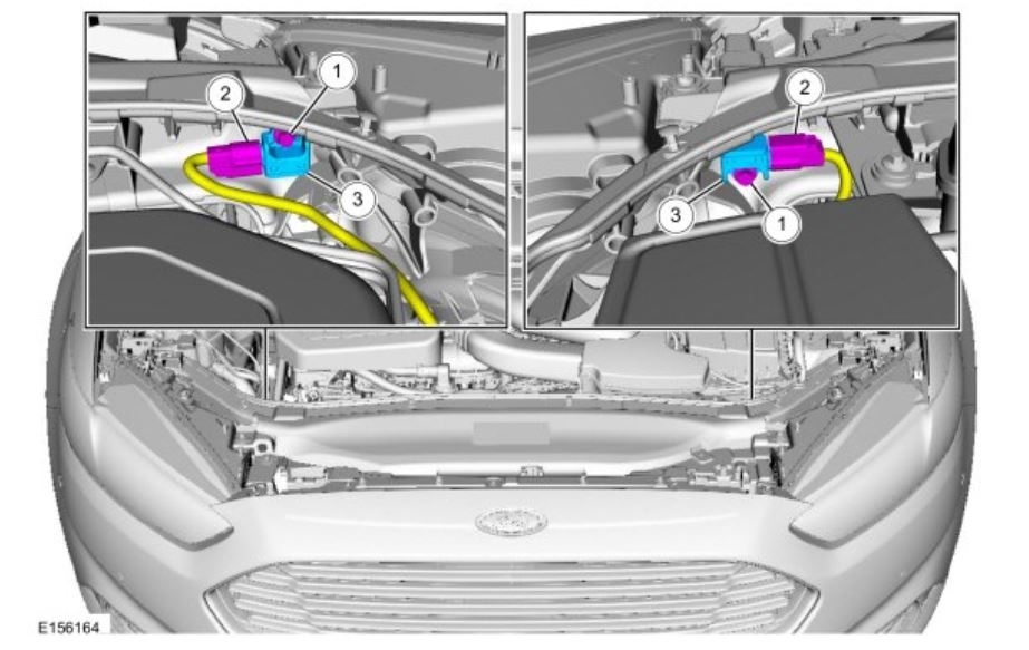
Front Impact Severity Sensor
The front impact severity sensors measure acceleration (g-rate) and are hardwired to the RCM (restraints control module). Mounting orientation is critical for correct operation of the front impact severity sensors.
Occupant Classification System (OCS)
The OCS (occupant classification system) is found only on the front passenger seat. The OCS (occupant classification system) classifies the size of the front passenger seat occupant.
The OCS (occupant classification system) is comprised of a silicone gel-filled bladder mounted between the seat cushion foam and pan, an OCSM (occupant classification system module) which is mounted to the seat frame, and a pressure sensor that is internal to the OCSM (occupant classification system module). Pressure is applied to the OCS (occupant classification system) bladder when weight of any occupant or object in the front passenger seat is present. The pressure is then transferred through a tube and sensed by the OCS (occupant classification system) pressure sensor and OCSM (occupant classification system module). The components of an OCS (occupant classification system) bladder system (bladder, tube, and OCSM (occupant classification system module) with integrated pressure sensor) are serviced as an assembly, and the OCS (occupant classification system) bladder system is serviced as a kit with the seat cushion and seat heater mat (if applicable).
The Belt Tension Sensor (BTS) is a Hall-effect sensor that modifies a reference voltage supplied by the OCSM (occupant classification system module). As the amount of tension applied to the belt varies, so does the voltage that returns to the OCSM (occupant classification system module). The Belt Tension Sensor (BTS) is part of the front passenger safety belt buckle and can only be serviced with the buckle.
Safety Belt Buckle Sensor
The safety belt buckles contain integrated sensors that are Hall-effect switches. The safety belt buckle sensors are serviced with the safety belt buckle.
Safety Belt Tension Sensor (BTS)
The safety Belt Tension Sensor (BTS) is a 3-wire Hall-effect sensor that is part of the front passenger safety belt buckle and cannot be serviced separately from the front passenger safety belt buckle assembly.
Seat Position Sensor
The seat position sensor is a Hall-effect sensor which indicates the position of the seat along the seat track. The sensor detects the presence of a shunt bracket on the track, indicating the seat has moved past a certain point in the adjustment range.
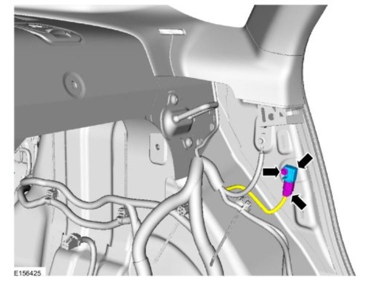
Side Impact Sensor - C-pillar
The C-pillar side impact sensors measure acceleration (g-rate), and are hardwired to the RCM (restraints control module). Mounting orientation is critical for correct operation of the C-pillar side impact sensors.
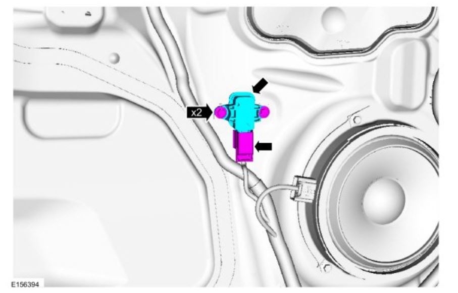
Side Impact Sensor - Front Door
The front door side impact sensors measure air pressure within the door in order to detect certain crashes, such as a side impact. Mounting position and orientation is critical for correct operation of the front door side impact sensors.
Driver Airbag
The driver airbag is a dual-stage airbag. Upon receiving a flow of current, it deploys at 1 of 2 different rates, depending upon vehicle impact severity and sensor input.
Passenger Airbag
The passenger airbag is a dual-stage airbag which deploys at 1 of 2 different rates depending upon vehicle impact severity and sensor input.
Passenger Airbag Canister Vent
The passenger airbag canister vent is a deployable device that is part of the passenger airbag. Canister venting controls the inflation rate of the passenger airbag and the escape rate of gases from the vent. The canister vent cannot be serviced separately from the passenger airbag.
Passenger Airbag Deactivation (PAD) Indicator
The PAD (passenger airbag deactivation) indicator is a LED (light emitting diode) which is hardwired to the RCM (restraints control module).
Safety Belt Inflator
The safety belt inflator is a pyrotechnic device that deploys upon receipt of current flow initiated by the RCM (restraints control module). It is a canister that releases inert gas to deploy the inflatable shoulder belt.
The safety belt inflators are attached to a bracket along with the second row safety belt buckles and cannot be serviced separately from the bracket and buckles. When replacing safety belt system components, use only the replacement parts specified in the parts catalog.
To diagnose any safety belt inflator Diagnostic Trouble Codes (DTCs):
Refer to: Airbag Supplemental Restraint System (SRS) See: Restraints and Safety Systems > Diagnostic Trouble Code Descriptions > DTC Chart: Restraint Control Module (RCM).
Safety Belt Retractor and Adaptive Load Limiter
The front passenger safety belt retractor is equipped with the adaptive load limiting feature that works in conjunction with the safety belt buckle pretensioner to control the tension of the front passenger safety belt in the event of a crash. The front passenger safety belt retractor is also referred to as the seatbelt load limiter.
To diagnose any adaptive load limiter Diagnostic Trouble Codes (DTCs):
Refer to: Airbag Supplemental Restraint System (SRS) See: Restraints and Safety Systems > Diagnostic Trouble Code Descriptions > DTC Chart: Restraint Control Module (RCM).
For any concerns regarding safety belt retractor function:
Refer to: Seatbelt Systems See: Seat Belt Systems > Symptom Related Diagnostic Procedures > Symptom Chart(s).
Safety Belt Retractor and Pretensioner
The safety belt retractor and pretensioner is a pyrotechnic device that removes excess webbing from the safety belts when deployed.
To diagnose any pretensioner Diagnostic Trouble Codes (DTCs):
Refer to: Airbag Supplemental Restraint System (SRS) See: Restraints and Safety Systems > Diagnostic Trouble Code Descriptions > DTC Chart: Restraint Control Module (RCM).
For any concerns regarding safety belt retractor function:
Refer to: Seatbelt Systems See: Seat Belt Systems > Symptom Related Diagnostic Procedures > Symptom Chart(s).
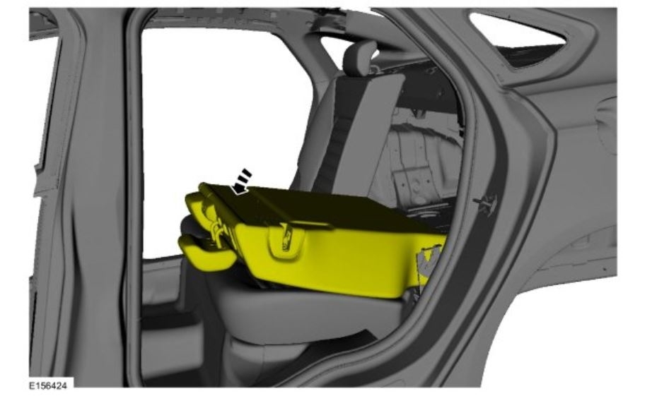
Side Air Curtain
The side air curtain is a single-stage airbag which is designed to protect the vehicle occupant(s) during certain side impact crashes. It deploys upon receipt of current flow, in conjunction with the seat side airbag.
Side Airbag
The side airbag is a single-stage airbag which deploys upon receipt of current flow. It is attached to the outboard side of each front seat and is used in conjunction with the side air curtain.
Clockspring
The clockspring allows for continuous electrical connections between the driver airbag and the RCM (restraints control module). A spiral-wound cable wraps around the center of the clockspring and as the steering wheel is turned, the spiral cable inside expands or contracts in diameter as the 2 halves of the clockspring turn.
Restraints Control Module (RCM)
NOTE: This vehicle may be equipped with SYNC(R), which contains the 911 Assist(TM) option. Refer to the Owner's Literature for information about this feature.
The RCM (restraints control module) monitors various sensor inputs and uses that data for controlling SRS (supplemental restraint system) outputs such as Belt-Minder(R) function and airbag deployment.
The RCM (restraints control module) includes a backup power supply. This feature provides sufficient backup power to deploy the airbags in the event the ignition circuit is lost or damaged during impact. The backup power supply depletes its stored energy approximately one minute after power and/or ground has been removed from the RCM (restraints control module).
The RCM (restraints control module) requires Programmable Module Installation (PMI) when being replaced. Refer to the diagnostic scan tool instructions to carry out Programmable Module Installation (PMI).
Refer to: Airbag and Seatbelt Pretensioner Supplemental Restraint System (SRS) - System Operation and Component Description See: Air Bag Systems > Components > Airbag and Seatbelt Pretensioner Supplemental Restraint System (SRS) - System Operation and Component Description.
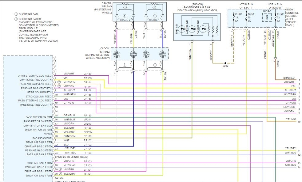
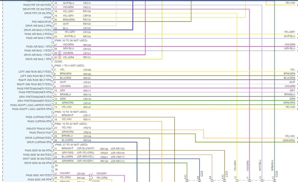
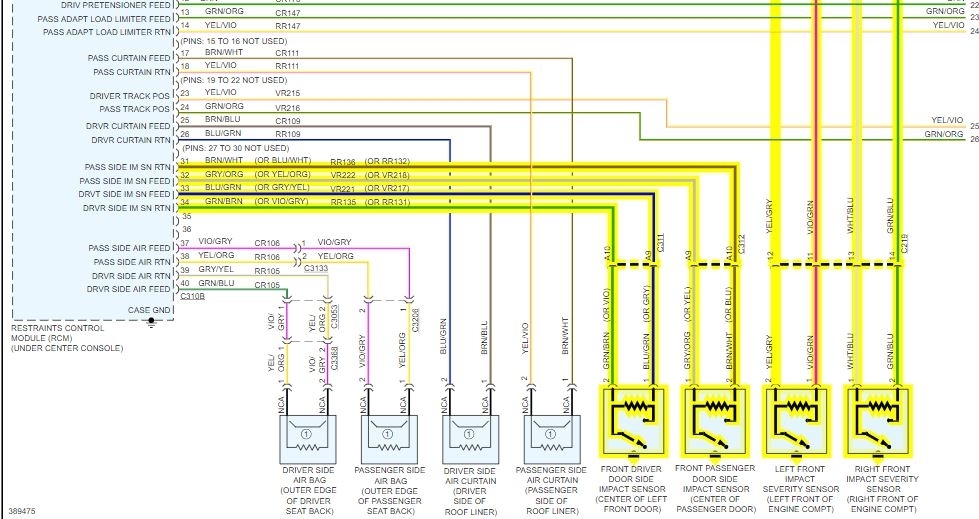
Images (Click to make bigger)
Wednesday, January 27th, 2021 AT 12:21 PM