Hi,
On many vehicles, it is external. On this vehicle, it's in the transmission and requires removal of the valve body to access.
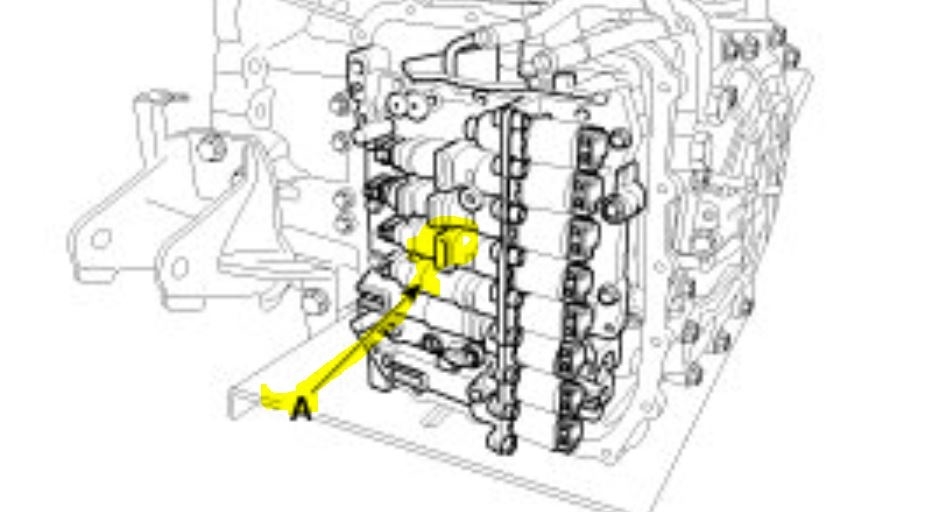
Here are the directions. The attached pics correlate with the directions. Also, the first pic I enlarged so you can better see its location. Sorry it's somewhat blurry.
__________________________________________
2013 Kia Optima L4-2.4L
Output Speed Sensor
Vehicle Powertrain Management Transmission Control Systems Sensors and Switches - Transmission and Drivetrain Sensors and Switches - A/T Transmission Speed Sensor Service and Repair Removal and Replacement Output Speed Sensor
OUTPUT SPEED SENSOR
Inspection
1. Check signal waveform of Input & output speed sensor using the GDS.
Specification:Refer to "Signal Wave Form" section.
Removal
1. Remove the battery and the battery tray.
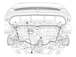
2. Remove the under cover (A).
Tightening torque:
7.8 - 11.8 N.M (0.8 - 1.2 kgf.M, 5.8 - 8.7 lb-ft)
pic 2
3. Replace new gasket and the plug after draining the automatic transaxle fluid by removing the drain plug.
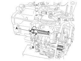
4. Remove the valve body cover (B) and eyebolt (A).
Tightening torque:
(A) 34.3 - 44.1 N.M (3.5 - 4.5 kgf.M, 25.3 - 32.6 lb-ft)
(B) 13.8 - 14.7 N.M (1.3 - 1.5 kgf.M, 9.4 - 10.8 lb-ft)
CAUTION:
Always replace the gasket of the eyebolt use new one whenever loosening eyebolt.
NOTE:
Remove installation bolts in the engine compartment first and then remove others under the vehicle
pic 3
5. Remove the plate and the detent spring (A) after removing the bolt.
Tightening torque:
24.5 - 35.3 N.M (2.5 - 3.6 kgf.M, 18.1 - 26.0 lb-ft)
pic 4
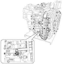
6. Remove the bolt (3ea) after disconnecting the solenoid valve connector (A) and the oil temperature sensor connector (B).
Tightening torque:
9.8 - 11.8 N.M (1.0 - 1.2 kgf.M, 7.2 - 8.7 lb-ft)
CAUTION:
Be careful not to damage the harness lock connector.
Pic 5
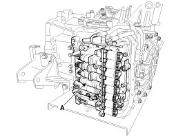
7. Remove the valve body assembly (A).
Tightening torque:
9.8 - 11.8 N.M (1.0 - 1.2 kgf.M, 7.2 - 8.7 lb-ft)
pic 6
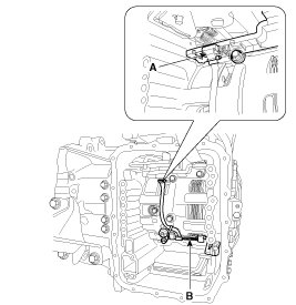
8. Disconnect the input & output speed sensor connector(A).
9. Remove the input & output speed sensor (B) after removing the bolts(2ea).
Tightening torque:
9.8 - 11.8 N.M (1.0 - 1.2 kgf.M, 7.2 - 8.7 lb-ft)
pic 7
Installation
1. Installation is the reverse of removal.
NOTE:
After replacement or reinstallation procedure of the valve body assembly, must perform procedures below.
- Continue to apply liquid gasket at application points at the valve body cover with 2.5mm (0.0984in.) Thickness.
Liquid gasket Part name :
Three bond 1281B or LOCTITE FMD-546(P/N : UM010CH046) or equivalent
- Adding automatic transaxle fluid.
____________________________________________
Let me know if this helps or if you have other questions.
Take care,
Joe
Images (Click to make bigger)
SPONSORED LINKS
Friday, November 29th, 2019 AT 9:42 PM