TEST TC-35A: NO VEHICLE SPEED SENSOR SIGNAL
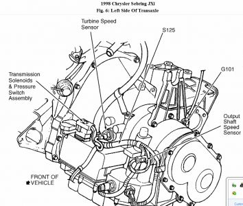
NOTE: For connector terminal identification, see CONNECTOR
IDENTIFICATION . For wiring diagram, refer to WIRING DIAGRAMS .
WARNING: Keep hands and feet clear of rotating wheels.
Raise and support vehicle under lower control arms, allowing drive wheels to spin free. Start
engine. Using scan tool, read Vehicle Speed Sensor (VSS). Put transmission in any forward
gear. If scan tool displays more than zero MPH, go to next step. If scan tool does not display
more than zero MPH, go to step 5).
1.
Condition to set trouble code is not present at this time. NO VEHICLE SPEED SENSOR
SIGNAL DTC sets if there is no signal from Vehicle Speed Sensor (VSS) for more than 11
seconds (without electronically controlled transmission) or no VSS signal is present from
Transmission Control Module (TCM) for more than 11 seconds (equipped with electronically
controlled transmission). If vehicle is NOT equipped with an electronically controlled
automatic transmission, go to next step. If vehicle is equipped with an electronically controlled
automatic transmission, possible causes are: open or shorted signal circuit, speedometer pinion
factor not programmed, output speed sensor circuit problem, failed Powertrain Control Module
(PCM) or failed TCM. Go to step 4).
2.
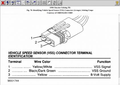
Possible causes are: open or shorted signal circuit, speedometer pinion damaged, open 8-volt
supply circuit, open sensor ground circuit, failed VSS, failed Powertrain Control Module
(PCM), faulty connections or wiring. Go to next step.
3.
Inspect all related wiring and connectors and repair as necessary. If no problems were found
with wiring and connectors, see INACTIVE TROUBLE CODE CONDITION under SELFDIAGNOSTIC
SYSTEM. Test is complete. Perform TEST VSS-VER . If related wiring and
connectors were repaired, Perform TEST VSS-VER .
4.
If vehicle is equipped with an electronically controlled automatic transmission, go to next step.
If vehicle is not equipped with an electronically controlled automatic transmission, go to TEST
TC-35B.
5.
Using scan tool, read transmission trouble codes. If transmission Diagnostic Trouble Codes
(DTCs) 50-58 are present or pinion factor is not programmed, repair transmission as required.
See appropriate article in AUTOMATIC TRANSMISSION Section. If transmission Diagnostic
Trouble Codes (DTCs) 50-58 are not present or pinion factor is programmed, go to next step.
6.
Turn ignition off. Disconnect Transmission Control Module (TCM) connector. Connect one
end of a jumper wire to TCM connector terminal No. 58. See TCM CONNECTOR WIRE
IDENTIFICATION table. Turn ignition on. Using scan tool, read VSS signal. While
observing scan tool display, tap other end of jumper wire to ground. If scan tool does not
display more than zero MPH, go to next step. If scan tool displays more than zero MPH, repair
transmission as required. See appropriate article in AUTOMATIC TRANSMISSION Section.
7.
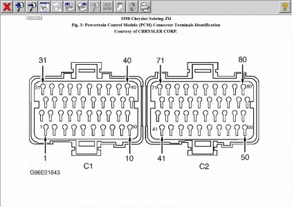
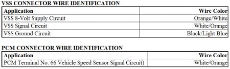
Turn ignition off. Disconnect PCM connector. Using an ohmmeter, check resistance of VSS
signal circuit between PCM connector terminal No. 66 and TCM connector terminal No. 58.
See TCM CONNECTOR WIRE IDENTIFICATION table. If resistance is less than 5 ohms,
go to next step. If resistance is 5 ohms or more, repair open VSS signal circuit. Perform TEST
VSS-VER .
8.
CRUISE CONTROL SYSTEMS - EXCEPT COUPE -1998 Chrysler Sebring JXi Page 1 of 2
4/23/2010
Using an ohmmeter, check resistance of VSS signal circuit between TCM connector terminal
No. 58 and ground. If resistance is less than 5 ohms, repair short to ground on VSS signal
circuit. Perform TEST VSS-VER . If resistance is 5 ohms or more, replace PCM. Perform
TEST VSS-VER .
9.
TCM CONNECTOR WIRE IDENTIFICATION
Application Wire Color
TCM Terminal No. 58 Vehicle Speed Sensor Signal Circuit) White/Orange
CRUISE CONTROL SYSTEMS - EXCEPT COUPE -1998 Chrysler Sebring JXi Page 2 of 2
4/23/2010
Apr 23, 2010 at 4:14 PM