I can give the instructions, but be aware that the cluster needs to be programmed. It may have theft information to relearn, or at a minimum the odometer and engine hours need to be installed.
Instrument Cluster Replacement
Removal Procedure
Remove the left closeout insulator panel. Refer to Instrument Panel Insulator Panel Replacement - Left Side .
Remove the knee bolster trim panel. Refer to Driver Knee Bolster Panel Replacement .
Remove the instrument panel cluster (IPC) bezel. Refer to Instrument Panel Cluster Trim Plate Bezel Replacement .
Remove the screws retaining the IPC to the I/P.
Partially remove the IPC from the I/P in order to gain access to the electrical connector.
Disconnect the electrical connector from the IPC.
Remove the IPC from the I/P.
Installation Procedure
Position the IPC to the I/P.
Connect the electrical connector to the IPC.
Install the IPC to the I/P.
Notice: Use the correct fastener in the correct location. Replacement fasteners must be the correct part number for that application. Fasteners requiring replacement or fasteners requiring the use of thread locking compound or sealant are identified in the service procedure. Do not use paints, lubricants, or corrosion inhibitors on fasteners or fastener joint surfaces unless specified. These coatings affect fastener torque and joint clamping force and may damage the fastener. Use the correct tightening sequence and specifications when installing fasteners in order to avoid damage to parts and systems.
Install the screws to the instrument panel cluster.
Tighten
Tighten the screws to 2.5 N ·m (22 lb in).
Install the IPC bezel. Refer to Instrument Panel Cluster Trim Plate Bezel Replacement .
Install the knee bolster trim panel. Refer to Driver Knee Bolster Panel Replacement .
Install the left closeout insulator panel. Refer to Instrument Panel Insulator Panel Replacement - Left Side .
If installing a new IPC. Refer to Service Programming System (SPS) in Programming.
Instrument Panel Cluster Trim Plate Bezel Replacement (Chevrolet)
Removal Procedure
Tilt the steering wheel to the full down position.
Remove the left closeout/insulator panel . Refer to Instrument Panel Insulator Panel Replacement - Left Side .
Remove the knee bolster trim panel. Refer to Driver Knee Bolster Panel Replacement .
Remove the screws retaining the bezel to the instrument panel.
Remove the bezel from the instrument panel.
If equipped, remove the transfer case shift control switch. Refer to Transfer Case Shift Control Switch Replacement in Transfer Case.
Remove the rear wiper washer switch. Refer to Rear Window Wiper and Washer Switch Replacement in Wipers Washer Systems.
If equipped, remove the cigar lighter or 12-volt power supply outlets. Refer to 12-Volt Accessory Power Receptacle Replacement in Power Outlets.
Remove the bezel from the vehicle.
Installation Procedure
If equipped, install the cigar lighter or 12-volt power supply outlets. Refer to 12-Volt Accessory Power Receptacle Replacement in Power Outlets.
Install the rear wiper washer switch. Refer to Rear Window Wiper and Washer Switch Replacement in Wipers Washer Systems.
If equipped, install the transfer case shift control switch. Refer to Transfer Case Shift Control Switch Replacement in Transfer Case.
Install the bezel to the instrument panel.
Notice: Refer to Fastener Notice in the Preface section.
Install the screws retaining the bezel to the instrument panel.
Tighten
Tighten the screws to 2.5 N ·m (22 lb in).
Install the knee bolster trim panel. Refer to Driver Knee Bolster Panel Replacement .
Install the left closeout/insulator panel. Refer to Instrument Panel Insulator Panel Replacement - Left Side .
Instrument Panel Insulator Panel Replacement - Left Side
Removal Procedure
Remove the 2 screws that retain the insulator panel to the instrument panel (I/P).
Release the insulator panel retaining clip from the I/P substrate.
Lower the insulator panel.
Remove the 2 data link connector (DLC) retaining screws.
Remove the DLC from the insulator panel.
Remove the splice pack from the insulator panel.
Remove the hazard and turn signal flasher from the insulator panel. Refer to Hazard and Turn Signal Flasher Replacement .
Remove the insulator panel from the I/P.
Installation Procedure
Position the insulator panel to the I/P.
Install the hazard and turn signal flasher to the insulator panel. Refer to Hazard and Turn Signal Flasher Replacement .
Install the splice pack to the insulator panel.
Position the DLC to the insulator panel.
Notice: Use the correct fastener in the correct location. Replacement fasteners must be the correct part number for that application. Fasteners requiring replacement or fasteners requiring the use of thread locking compound or sealant are identified in the service procedure. Do not use paints, lubricants, or corrosion inhibitors on fasteners or fastener joint surfaces unless specified. These coatings affect fastener torque and joint clamping force and may damage the fastener. Use the correct tightening sequence and specifications when installing fasteners in order to avoid damage to parts and systems.
Install the DLC retaining screws.
Tighten
Tighten the DLC retaining screws to 2.5 N ·m (22 lb in).
Install the insulator panel tabs to the cowl slots.
Raise the insulator panel to the I/P.
Install the insulator panel retaining clip to the I/P substrate.
Install the 2 screws that retain the insulator panel to the I/P.
Tighten
Tighten the screws to 2.5 N ·m (22 lb in).
Driver Knee Bolster Panel Replacement
Removal Procedure
Remove the left closeout/insulator panel. Refer to Instrument Panel Insulator Panel Replacement - Left Side .
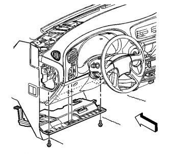
Remove the 4 trim panel retaining screws.
Release the clips that retain the trim panel to the IP.
Remove the trim panel from the IP.
Installation Procedure
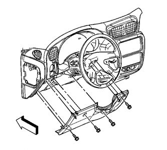
Position the trim panel to the IP.
Seat the clips that retain the trim panel to the IP.
Notice: Use the correct fastener in the correct location. Replacement fasteners must be the correct part number for that application. Fasteners requiring replacement or fasteners requiring the use of thread locking compound or sealant are identified in the service procedure. Do not use paints, lubricants, or corrosion inhibitors on fasteners or fastener joint surfaces unless specified. These coatings affect fastener torque and joint clamping force and may damage the fastener. Use the correct tightening sequence and specifications when installing fasteners in order to avoid damage to parts and systems.
Install the 4 trim panel retaining screws.
Tighten
Tighten the screws to 2.5 N ·m (22 lb in).
Install the left closeout/insulator panel. Refer to Instrument Panel Insulator Panel Replacement - Left Side .
Nov 9, 2010 at 11:55 PM