Hi,
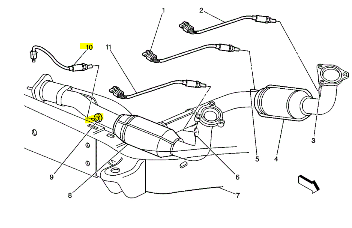
The down stream sensor is after the catalytic converter. If you look at the attached pic, I highlighted where it goes. If you look at the picture, bank 1 sensor 1 goes where number 3 is pointing and pic 6 shows bank 2 sensor 1.
Here are the directions for replacement. The remaining pics below correlate with the directions.
____________________________________
2004 Chevy Truck Tahoe 4WD V8-5.3L VIN T
Heated Oxygen Sensor (HO2S) Replacement Bank 1 Sensor 2
Vehicle Powertrain Management Sensors and Switches - Powertrain Management Sensors and Switches - Computers and Control Systems Oxygen Sensor Service and Repair Procedures Heated Oxygen Sensor (HO2S) Replacement Bank 1 Sensor 2
HEATED OXYGEN SENSOR (HO2S) REPLACEMENT BANK 1 SENSOR 2
HEATED OXYGEN SENSOR (HO2S) REPLACEMENT BANK 1 SENSOR 2
REMOVAL PROCEDURE
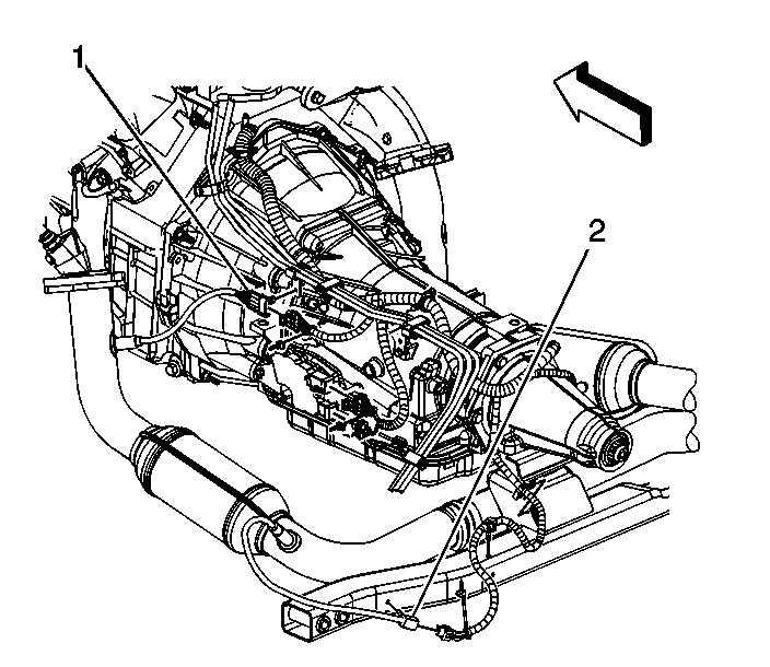
pic 2
1. Raise and suitably support the vehicle. Refer to Vehicle Lifting.
2. If equipped, disconnect the fuel composition sensor electrical connector.
3. Disconnect the connector position assurance (CPA) retainer.
NOTE: Refer to Heated Oxygen and Oxygen Sensor Notice in Service Precautions.
4. If equipped with a fuel composition sensor, remove the heated oxygen sensor (HO2S) electrical connector from the fuel line clip.
5. If equipped with a 4.8L or 5.3L engine, disconnect the HO2S electrical connector (2).
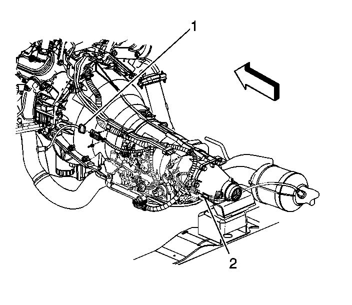
pic 3
6. If equipped with a 6.0L engine, disconnect the HO2S electrical connector (2).
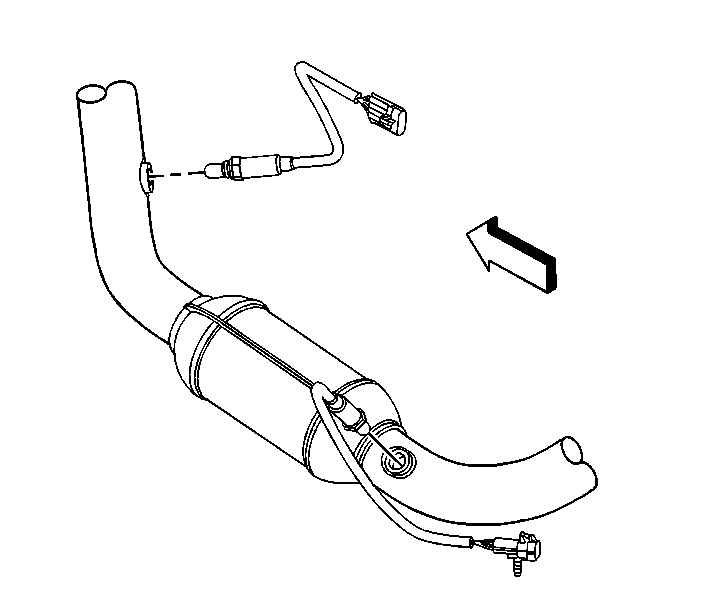
pic 4
7. Remove the HO2S.
NOTE: Refer to Excessive Force and Oxygen Sensor Notice in Service Precautions.
INSTALLATION PROCEDURE
IMPORTANT: A special anti-seize compound is used on the HO2S threads. The compound consists of liquid graphite and glass beads. The graphite tends to burn away, but the glass beads remain, making the sensor easier to remove. New, or service replacement sensors already have the compound applied to the threads. If the sensor is removed from an exhaust component and if for any reason the sensor is to be reinstalled, the threads must have anti-seize compound applied before the reinstallation.
pic 5
1. If reinstalling the old sensor, coat the threads with anti-seize compound GM P/N 12377953, or equivalent.
NOTE: Refer to Component Fastener Tightening Notice in Service Precautions.
2. Install the HO2S.
Tighten the sensor to 42 N.m (31 lb ft).
pic 6
3. If equipped with a 6.0L engine, connect the HO2S electrical connector (2).
pic 7
4. If equipped with a 4.8L or 5.3L engine, connect the HO2S electrical connector (2).
5. If equipped with a fuel composition sensor, install the HO2S electrical connector to the fuel line clip.
6. Disconnect the CPA retainer.
7. If equipped, connect the fuel composition sensor electrical connector.
8. Lower the vehicle.
_____________________
I hope this helps. Let me know if you have other questions.
Take care and God Bless,
Joe
Images (Click to enlarge)
Feb 25, 2021 at 5:47 PM