Sounds like the ignition module, test like this:
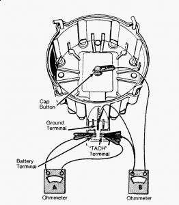
INTERMITTENT SYSTEM PROBLEMS 1. Check spark at 2 plug wires using Spark Tester (J-26792). If no spark occurs, go to ENGINE WILL NOT START procedure. If spark occurs from 1 or both spark plug wires, check pick- up coil with ohmmeter, Refer to testing pick-up coil in TESTING - COMPONENT TESTS . 2. If pick-up coil is defective, replace it. If it is good, check for dwell increase from high to low RPM. If dwell did not increase, replace electronic module. 3. If dwell did increase, and trouble is not found, check fuel, coil and plug wires, also cap and plugs. ELECTRONIC MODULE An approved electronic module tester must be used to test the module. Use Module Tester (J-24642- E). Follow manufacturer's instructions. INTEGRAL IGNITION COIL Chevrolet & GMC Only 1. The ignition coil can be tested for shorted and open windings using an ohmmeter. Connect the ohmmeter between the positive terminal and coil frame (ground). Use the high resistance scale. The ohmmeter should indicate infinite resistance. If not, replace the coil. 2. Connect the ohmmeter between the positive and negative terminals. Use the low resistance scale. The ohmmeter should indicate zero, or nearly zero. If not, replace the coil. 3. Connect the ohmmeter between the negative terminal and the high voltage terminal. Use the high resistance scale. The ohmmeter should indicate less than infinite resistance. If not, replace the coil. See Fig. 6 . NOTE: When installing a new HEI module, use silicone lubricant on back of module and on housing under module.
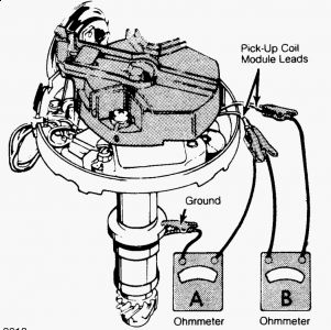
PICK-UP COIL 1. Identify the 2 pick-up coil lead wires. On most applications, these wires are 1 Green and 1 White. The pick-up coil connector must be disconnected from the module, then an ohmmeter is connected to 1 connector terminal and to the distributor housing. Next, the ohmmeter is connected to both terminals. 2. Connect external vacuum source to vacuum advance unit. If vacuum advance unit is inoperative, replace unit. Connect an ohmmeter, using mid scale, to either pick-up coil terminal and the distributor housing. 3. Operate the vacuum pump and observe the ohmmeter throughout vacuum range. Reading should be infinite at all times. If not, replace pick-up coil. See meter "A" in Fig. 8 . 4. Connect ohmmeter to both pick-up coil connector terminals. Operate vacuum pump and observe ohmmeter throughout the vacuum range. Also, flex wires by hand to locate any intermittent defective connections at pick-up coil and at terminals on ends of wires. 5. The ohmmeter should indicate a constant resistance in the 500-1500 ohm range at all times. If not, replace the pick-up coil. See meter "B" in Fig. 7 NOTE: Operation of the vacuum mechanism may cause a trigger wheel tooth and the pick-up coil pole piece to align and the ohmmeter pointer to deflect. This deflection should not be interpreted as the result of a faulty pick-up coil.
Jan 31, 2010 at 2:06 PM