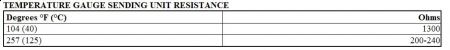
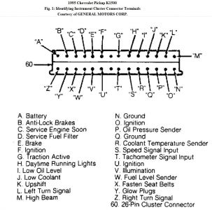
SPEEDOMETER & ODOMETER Speedometer & Odometer Are Inaccurate Replace VSS buffer. Speedometer & Odometer Do Not Operate Properly 1. Unplug VSS buffer, located under passenger side end of instrument panel. Turn ignition on. Check for battery voltage between harness connector Pink/Black wire and ground. If battery voltage exists, go to next step. If battery voltage does not exist, repair short or open in Pink/Black wire. 2. Check for battery voltage between Pink/Black wire and Black/White wire at harness connector. If battery voltage exists, go to next step. If battery voltage does not exist, repair open in Black/White wire. 3. Raise and support vehicle with drive wheels off ground. Start engine. Shift transmission to Drive. Check for AC voltage between Purple/White and Light Green/Black wires of harness connector. 4. Voltage should change as wheel speed increases or decreases. If AC voltage does not exist, check for short or open in Purple/White and Light Green/Black wires. If wiring is okay, replace vehicle speed sensor. 5. Turn ignition off. Reconnect VSS buffer. Start engine. Put transmission into gear. Backprobe Blue/Black and Black/White wires at VSS buffer connector. If AC voltage varies with RPM change, replace VSS buffer. 6. Backprobe Red/White and Black/White wires at VSS buffer connector. If AC voltage varies with RPM change, replace VSS buffer. If all foregoing checks are okay, replace instrument cluster. Fig. 1: Identifying Instrument Cluster Connector Terminals Courtesy of GENERAL MOTORS CORP. CHECK GAUGES LIGHT Light Inoperative With High Coolant Temperature Check bulb. Check for inoperative coolant temperature gauge and circuit. Repair/replace as necessary. If temperature gauge and circuit are okay, replace defective instrument cluster. Light Inoperative With Low Oil Pressure Check bulb. Check for inoperative oil pressure switch. Repair or replace as necessary. If gauge and circuit are okay, replace defective instrument cluster. Light Always On Check bulb. Check for inoperative coolant temperature and oil pressure gauge circuits. Replace coolant temperature and/or oil pressure gauge if necessary. If coolant temperature and oil pressure gauges and circuits are okay, replace defective instrument cluster. COOLANT TEMPERATURE GAUGE (GASOLINE) Gauge Indicates Cold When Engine Is Hot 1. Check for blown GAGES fuse. Unplug connector from coolant temperature sending unit. Turn ignition on. Connect sending unit lead to ground. If gauge indicates HOT, go to next step. If gauge does not indicate HOT, check for open in sending unit lead. If sending unit lead is okay, replace cluster. 2. Reconnect sending unit. If gauge now indicates COLD, inspect sending unit connection. If connection is okay, replace sending unit. After replacing sending unit, if gauge still indicates COLD with hot engine, gauge is defective. Replace cluster. Gauge Indicates Hot When Engine Is Cold 1. Turn ignition on. Unplug connector from temperature gauge sending unit. If gauge indicates COLD, replace sending unit. 2. If temperature gauge continues to indicate HOT, check for short to ground in wiring between sending unit and gauge. If circuit is okay, replace cluster. Gauge Indications Are Inaccurate 1. Check wiring for corroded or loose connections. Clean and tighten terminals and connections as necessary. Check for high resistance in temperature sending unit ground circuit. If terminals, connections, and ground circuit are okay, go to next step. 2. Unplug connector from temperature gauge sending unit. Measure sending unit resistance at specified temperatures. See the TEMPERATURE GAUGE SENDING UNIT RESISTANCE table. If measurements are not as specified, replace temperature gauge sending unit.
3/25/2010 ...
Mar 25, 2010 at 2:57 PM