Charging system

Tiny
JHB15001
  • MEMBER
  • 1994 FORD E-SERIES VAN
  • 7.9L
  • V8
  • 2WD
  • AUTOMATIC
  • 50,000 MILES
Replaced alternator, checked wiring have 12 volts to main on alternator and 12 volts to yellow/white on a-terminal and nothing to green/red wire to I terminal on alternator. Traced this wire to instrument cluster and have continuity from plug on cluster to I terminal on alternator. Checked bulb on cluster and is good. Am I supposed to have voltage on this wire? Is it possible the ristorante on back of cluster is bad.
Tuesday, October 22nd, 2019 AT 4:12 PM

6 Replies

Tiny
CARADIODOC
  • MECHANIC
  • 33,754 POSTS
I can't find any reference to a 7.9L engine, so I went with a 7.5L. If you have a diesel engine, I'll need to look for a different diagram.

The first diagram shows the entire charging system. The next two are just the same thing, but enlarged. The first step is to check for full battery voltage on the large output wire and the yellow field terminal. Those should be there all the time, as you found.

The secret to this system is the light green / red wire where you found 0 volts. With the ignition switch in the "run" position, current flows through the dash warning bulb, through that wire, then to the voltage regulator inside the generator. Roughly 10 volts is dropped across the bulb, so it turns on. That leaves about 2 volts on the light green / red wire, which you're missing. That is the regulator's turn-on signal, then it starts allowing current to flow through the yellow / white wire, then through the path shown in the fourth diagram. As it flows through the field winding, an electromagnetic field is set up around it.

You need three things to generate a current mechanically, that is a piece of wire, (a coil is more efficient; that's the stator windings), a magnet, in this case the field winding, and most importantly, movement between the two. That's why we have to spin the field winding with a belt.

At its maximum, which is rarely reached, the field circuit will draw 3 amps. Think of the regulator as a variable resistor that limits current flow through the field winding. The regulator senses system voltage on the yellow / white wire, then it causes the regulator to be as high a resistance as necessary to weaken the magnetic field, thereby reducing output voltage and current to the desired values.

Once the engine is running and the generator has started producing output current, a sample is fed back to the regulator on the short white / black wire. Now it knows the system is working, so it switches full charging voltage, 13.75 to 14.75 volts, onto the light green / red wire. With full voltage on that wire, and the same voltage on the other side of the warning light bulb through the ignition switch, the net difference is 0 volts, so the warning light turns off.

The best clue comes from watching that warning light. If it doesn't turn on when you turn the ignition switch to "run", there is a break in that light green / red circuit. It could be the bulb is burned out, but the resistor you asked about provides an alternate path for that start-up signal. Those resistors are typically a lot higher in resistance compared to that of the bulb, but sufficient current can still get through to tell the regulator to turn on. In this case the only symptom would be the warning light never turns on. You can verify the rest of the charging system is working by just measuring the battery voltage. With the engine running, you must find between 13.75 and 14.75 volts.

Another more time-consuming way to see if the charging system is working is to measure the voltage on the white / black wire the regulator uses for that purpose. With the engine running and the charging system operating properly, you'll find very close to half of battery voltage on the white / black wire, or around 7 volts.

My suspicion is there is a break in the light green / red wire. The only other possibility is a break in the red / light green wire between the ignition switch and the bulb. That would be very unusual. That circuit feeds other things, so you'd have more symptoms than a dead charging system. A better suspect would be a crack on the copper trace on the back of the instrument cluster.

A continuity test on the light green / red wire is not a good test for this type of problem. All you need is one tiny strand of wire remaining intact to get a good reading, but that won't allow enough current to flow. That 2 volts we expect to see at the regulator will be dropped across the bad spot in that wire. Leaving you with essentially 0 volts on the turn-on circuit. Voltage readings are much more valuable.
Was this
answer
helpful?
Yes
No
+1
Tuesday, October 22nd, 2019 AT 6:22 PM
Tiny
SCGRANTURISMO
  • MECHANIC
  • 4,897 POSTS
Hello,

If you have battery voltage at the instrument cluster connector C233 Pin 11B then you should have battery voltage at Pin 12B as well. If not then the instrument panel is bead and need to be replaced. In the diagrams down below I have included a wiring diagram of the charging system on your vehicle as well as a diagram of Connect C233 as well as a callout for it also. I have also included a guide explaining the proper way to check for voltage at electrical connectors as well. Please get back to us with what you are able to find out and we will go from there.

Thanks,
Alex
2CarPros
Was this
answer
helpful?
Yes
No
+1
Tuesday, October 22nd, 2019 AT 6:32 PM
Tiny
JHB15001
  • MEMBER
  • 3 POSTS
Just want to say thank you very much. Great information from both replies. So with that being said, I took instrument cluster completely out and checked what you suggested. I put back together and charging I got 14.5v on battery.I did call around junk yards for cluster and found one out of state for $45.00. I think I’ll get and install. What are your thoughts?
Was this
answer
helpful?
Yes
No
Wednesday, October 23rd, 2019 AT 4:13 PM
Tiny
CARADIODOC
  • MECHANIC
  • 33,754 POSTS
Bad idea. There has to be an intermittent break. That should be located and repaired. It could indeed be a break on the instrument cluster, especially if it uses a flexible plastic laminate with the copper traces embedded in it, but it could also be between two mating terminals that plug into the cluster. We won't be happy if you replace the cluster and the problem occurs again.

The same type of thing happens with older tvs. A common problem was the brightness changing when you walked across the floor. Unplug the "video" module, look at it, scratch your head, plug it back in, and the problem was gone, .. For a few weeks, then it came back. The cause was a light film of corrosion building up between the matting terminals. By simply removing and reinstalling the module, the scratching action cleaned up a small contact area so the intermittent connection didn't exist, until that corrosion built up again. The proper fix was to scrub the contacts, then squeeze the pins tighter to make a more solid connection. Replacing the module would also probably have solved it, but that was an unnecessary expense.

For my Automotive Electrical classes, I built over a dozen "bugged" cars for my kids to diagnose. All of those bugs had causes identical to what we really find on customers' cars. One of those was a hairline break on the flexible circuit film on the back of a GMC truck instrument cluster. When switched in, that bug also caused the voltage regulator in the generator to not start up, just like is happening with your van. GM has one more designed-in potential problem in that the plug for the cluster slides into a socket with another flexible print that is just ripe for developing poor connections. We read all the time about recurring problems related to clusters, and you have to wonder how many of those are caused by that poor design.

Those are the types of things that might seem to solve a problem by replacing the cluster, but it was actually just the removal and reinstallation that was the real solution. Before you spend money on something that might not be needed, look closely at the copper traces leading both ways from the "Battery" bulb. This is a real basic circuit that should not be too difficult to diagnose.
Was this
answer
helpful?
Yes
No
Wednesday, October 23rd, 2019 AT 6:59 PM
Tiny
JHB15001
  • MEMBER
  • 3 POSTS
I agree with your reply, what do you recommend to clean, contact cleaner spray or rubbing alcohol applied by a q-tip.
Was this
answer
helpful?
Yes
No
Saturday, October 26th, 2019 AT 9:05 AM
Tiny
CARADIODOC
  • MECHANIC
  • 33,754 POSTS
Depends on what you find. If you find a hairline break on a flexible copper trace, you'll need to scratch off the clear coating to get down to the copper, then bridge the break with a blob of solder. We used to run into this a lot with older tvs. To prevent a repeat failure, use a small hot soldering iron, melt a little solder on each side of the crack, then go back and melt in a piece of wire. I use a long piece so I have something to hold onto, then you can cut off the excess when you're done. It only needs to be a quarter inch long. If you don't put that wire in there, a crack will form in the solder over time.

Heat is the deadly enemy of transistors, and it can damage the plastic with the copper traces in it. Many people think it's safer to turn down the temperature on their soldering iron, but that is what leads to the damage. It takes so long for the solder to melt, that by the time it does, the damage has had time to occur. With a nice hot iron, the solder will melt quickly so you can get in, get out, and get it over with before much heat makes its way into the plastic.

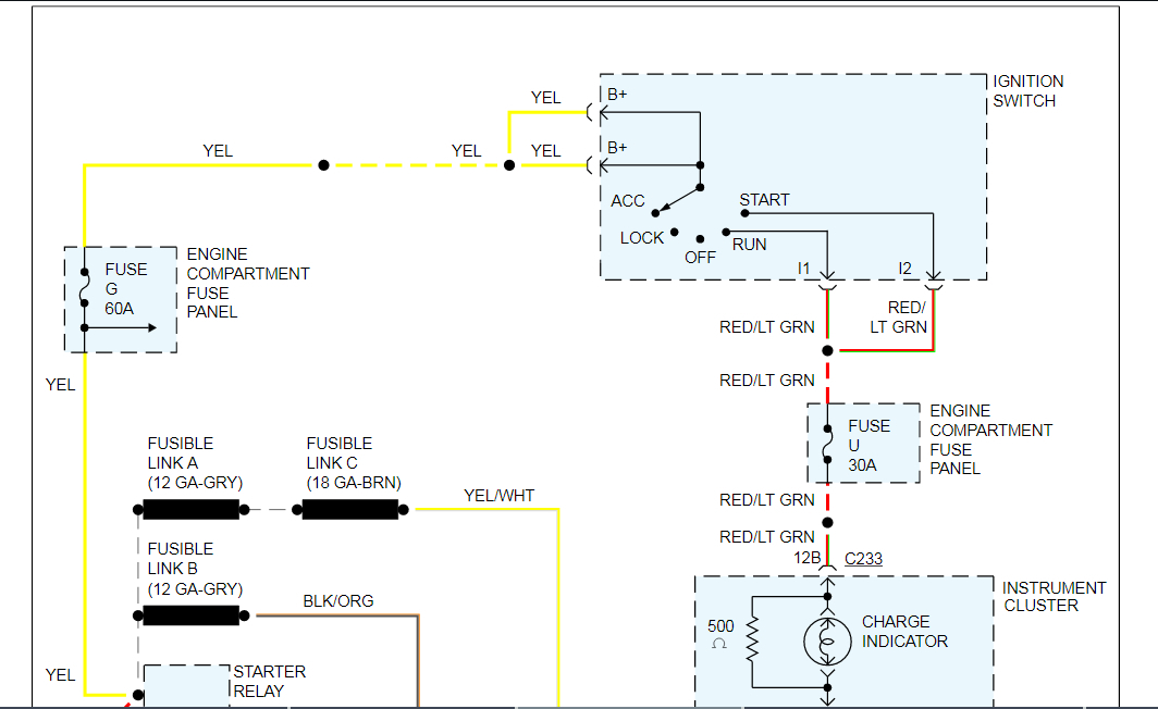
Once you've seen one of these breaks and know what they look like, they're usually pretty easy to spot. Most of the time they occur where the copper trace becomes real narrow, or where the flexible print bends around a corner. This is real common today on a lot of rear tail light housings too. If you don't see a break, use your ohm meter to measure the two circuits. Start at the "Battery" light bulb socket, then follow each trace back to a connector terminal. Those are the points to measure for continuity. You can check the bulb too, but there is about a 500 ohm resistor next to the bulb to provide an alternate path for the regulator's start-up signal if the bulb burns out.

GM trucks have the same kind of flexible plastic sheet stuffed into the opening where the instrument cluster's plug slides in. If you have something similar, look at the plug on the cluster, and you should see the terminals are spring-metal strips. Lightly sand those shiny, then use a small pick to pull those strips out a little so they put more pressure on the flexible print. Lightly sand those bare copper terminals on the print too.

Chrysler uses pins crimped to a hard, regular circuit board on the back of the cluster. On older vehicles, you hold the cluster up to the dash, then reach behind it to connect two plugs. On newer models, those terminals sit in a plastic box with angled sides that guide the plug into it as you slide the cluster into the dash. Those terminals are soldered to the circuit board, but they are well-known for developing broken solder connections. Those were a big part of what kept us in business at the tv repair shop. I only repaired one of these clusters, and I can't remember if I had to unbolt the circuit board and flip it over to see the broken connections. It seems to me it wasn't that difficult or time-consuming. This type of circuit board usually has copper traces on both side, and part of a circuit on one side is connected to the other part on the other side by lining the hole with copper. Once the terminal is inserted and it is soldered, that solder flows along the copper to show up on both sides of the board. You can get pretty aggressive with the soldering iron on those. You'll see the solder melt, then add a little new solder to the joint. The flux in the new solder will help it to melt the old solder on the backside of the board, so both sides get repaired at the same time. That's the only way to do it when the terminals are in that plastic box and you can't see the solder under that box.

If you have terminals that are crimped to the circuit board, vibration is going to cause them to loosen over time. Shine up the terminals and the copper traces right where the terminals go through it, then melt some solder to the connections. Here too, there can be additional copper traces on the backside. The solder should flow through the hole and get to the back traces. No need to solder on both sides.

We kind of jumped ahead by not actually diagnosing this yet. The first thing to do is to unplug the three-wire connector at the generator, turn the ignition switch to "run", then check for 12 volts on the light green / red wire. You found 0 volts on there originally, but I'm betting that was with the plug connected. If you find 12 volts now, use a paper clip and / or jumper wire and ground that wire. Doing so should make the "Battery" light turn on. If it does, that entire circuit is okay, and the suspects are that terminal is stretched in the plug so it's not making contact with the mating terminal in the regulator's plug, or the regulator is defective. There are other tests we can do on the regulator and internal brushes, but that would be the plan of attack if you had found 2 volts on the light green / red wire. We'll know more once you check for voltage with plug disconnected.

If the "Battery" light doesn't turn on when you ground the light green / red wire, see if you can figure out which is the red / light green wire feeding that bulb from the ignition switch, then check that one for 12 volts. If it's missing there, a good suspect would be the connector at the base of the steering column. Those terminals often get hot and degraded. There's only a small fraction of an amp flowing through the light bulb. That by itself isn't enough to overheat a terminal, but that circuit coming from the ignition switch is feeding other things that could be drawing high current.

It only takes one tiny strand of wire, or a carbon track around a burned pair of mating terminals to pass enough current for a digital voltmeter to detect 12 volts, but you won't get enough current to turn on the voltage regulator. This often makes digital voltmeters give false readings. If you use a test light instead, they work by using current from the circuit under test, so they will be more accurate for this type of problem. If you can't get enough current to turn on the regulator, the test light won't light up either. The disadvantage of the test light is it doesn't show the exact voltage, but that's not important here. We just need to know if we have something or nothing.

As for chemicals, the only place I use rubbing alcohol is for cassette player heads. It will melt most plastic parts including flexible circuits. For car radios with sealed volume controls that don't work or make the volume change the wrong way, I have a special contact cleaner I call "nuclear waste" so people will leave it alone. It cost my boss $55.00 for one gallon in the mid '80s, but it hasn't been available since then. He gave me enough to fill a little squeeze bottle. That will have to last me the rest of my life. One drop will fix a volume control after soaking in for a few minutes. Regular contact cleaners evaporate too quickly.

For the copper circuits and terminals that need to be shined up, I would use "Tuner Cleaner" which is a special cleaner we used on the old mechanical tv channel selectors. That was another one of our common jobs. Today, rather than run around my shop trying to find a can of that stuff, I just use my fingers to wipe off any powder left from sanding the points. With all the electronics I repair, I really don't use chemicals very much.
Was this
answer
helpful?
Yes
No
Saturday, October 26th, 2019 AT 4:21 PM

Please login or register to post a reply.

Sponsored links