Charging issue

Tiny
BOBBYB69
  • MEMBER
  • 2000 MAZDA MPV
  • 2.3L
  • 6 CYL
  • 2WD
  • AUTOMATIC
  • 290,000 MILES
Hi, my vehicle has gone through five alternators. And yes they all tested bad. So when it happened a sixth time I just tore out the alternator and replaced it with a good used working one. No charge still. The one I took out was good this time. Now I have seen something about it is probably my PCM. Can someone please help me get issue repaired?
Thursday, February 14th, 2019 AT 8:22 PM

12 Replies

Tiny
JACOBANDNICKOLAS
  • MECHANIC
  • 108,200 POSTS
Hi and thanks for using 2CarPros.

First, confirm the 10 amp meter fuse behind the kick panel is good. See the attached picture. Next. If the battery is good (and I know it is new) confirm that there is no corrosion or damage at the plug on the alternator, which is not uncommon.

I attached pictures of the fuse and its location. Also, pictures 3 and 4 are of the entire charging circuit. I had to break it into two sections for it to fit. I did overlap it so you could follow it. The last two pictures show the back of both the internally regulated and computer regulated. See if you can determine which one you have. Picture 5 is the internally regulated.

Let me know what you find. Also, there are two different alternators this can have. One is internally regulated and the other is computer regulated. Make sure they are providing you with the correct one.

Let me know what you find or if you have other questions.

Take care,
Joe
Was this
answer
helpful?
Yes
No
+1
Friday, February 15th, 2019 AT 8:32 PM
Tiny
BOBBYB69
  • MEMBER
  • 37 POSTS
Hey Joe our a Blessing. I gave up for awhile (to keep my sanity lol) and been driving my play truck for work. I know shame on me. Anyhoo I am diving back in and realized I did a bonehead stunt. My two wire plug was broke and when I replaced it I did not mark which side is w/l and which is w/r. For the life of me I cannot find a picture online. Might you have one?
Many Thanks, Bobby B
Was this
answer
helpful?
Yes
No
Friday, March 8th, 2019 AT 6:52 PM
Tiny
BOBBYB69
  • MEMBER
  • 37 POSTS
And yes sir battery is six or seven months new.
Was this
answer
helpful?
Yes
No
Friday, March 8th, 2019 AT 6:54 PM
Tiny
JACOBANDNICKOLAS
  • MECHANIC
  • 108,200 POSTS
I attached a portion of the schematic I have. One wire is white and red, the other is white and blue. Let me know if this is what you needed.

Take care,
Joe
Was this
answer
helpful?
Yes
No
Friday, March 8th, 2019 AT 7:05 PM
Tiny
BOBBYB69
  • MEMBER
  • 37 POSTS
I got that from your first message and Thanks. I need a picture of the actual plug to know which wire goes where. My wires got torn out of my plug and the replacement ones are not the same color. Cheers
Was this
answer
helpful?
Yes
No
Friday, March 8th, 2019 AT 7:12 PM
Tiny
JACOBANDNICKOLAS
  • MECHANIC
  • 108,200 POSTS
Is this what you need?

From backside of connector, white/blue wire at the P terminal, and white/red at the D terminal.

Let me know if this helps.

Joe
Was this
answer
helpful?
Yes
No
+1
Friday, March 8th, 2019 AT 9:03 PM
Tiny
BOBBYB69
  • MEMBER
  • 37 POSTS
I do believe so, when I look at the plug is the bump on top the clip that locks it into place? My new plug has the red wire closer to the firewall and the brown wire faces the front of the engine. So I'm guessing white/red goes to red and white/light blue goes to brown. Also, I have 12 volts on the white/red wire and approximately 1 volt on the white/light blue wire. Does that sound correct? From what I've read it seems to be. I have continuity on main wire from alternator wire to battery. I am going to check for voltage on the alternator main wire but the engine does go bad if I take the positive wire off of battery. I am going to check all fuses again. Also again I want to know if you accept tips/donations for your help?
Many thanks and Blessings, Bobby B
Was this
answer
helpful?
Yes
No
Saturday, March 9th, 2019 AT 1:17 PM
Tiny
JACOBANDNICKOLAS
  • MECHANIC
  • 108,200 POSTS
Welcome back:

No tips. A long time ago, the owner's mother said he should do something to help people with car problems. This is the result.

And yes, that bump is the locking clip.
Was this
answer
helpful?
Yes
No
+2
Monday, March 11th, 2019 AT 3:39 PM
Tiny
BOBBYB69
  • MEMBER
  • 37 POSTS
Hi again JACOBANDNICKOLAS, How are y'all? Good here. My PCM is the problem with my van not charging. Thank you so much for the help. Also as y'all see above y'all said no to a tip. The reason I offered was 90% y'all's help was awesome and 10% because I saw this on y'all's site and wanted to help. Y'all's member DAVE H Made the comment thanks for the donation so I presumed y'all took tips. Anyway do y'all have any recommendations for who to go to to get my PCM rebuilt/replaced?
Thanks again and God Bless. Bobby B
Was this
answer
helpful?
Yes
No
Saturday, April 20th, 2019 AT 12:16 PM
Tiny
JACOBANDNICKOLAS
  • MECHANIC
  • 108,200 POSTS
Welcome back:

That wasn't necessary, but thank you very much. As far as a location for the repair, I'm not sure where you are located. However, I will tell you to take it to someone that is reputable. Chances are the one you have will not be repairable. Don't get one online. Too many bad things have happened. LOL

Take care of yourself, and if I helped, you are very welcome.

Have a great Easter,

Joe
Was this
answer
helpful?
Yes
No
+1
Saturday, April 20th, 2019 AT 5:12 PM
Tiny
BOBBYB69
  • MEMBER
  • 37 POSTS
I'm in Colorado, guess that would help. Happy Easter to you and your family.
Bobby B
Was this
answer
helpful?
Yes
No
Saturday, April 20th, 2019 AT 5:38 PM
Tiny
JACOBANDNICKOLAS
  • MECHANIC
  • 108,200 POSTS
Bobby:

I've never been to Colorado, but have seen some spectacular pics. Maybe some day. Again, make sure you find someone you can count on for this replacement.

Just in case you want to do it yourself or just wanted to know what was involved, here are the directions for removal. Replacement is the opposite of removal. If you do it yourself, make sure the PCM is the correct one and ask the seller if it needs programmed. I believe this one can be purchased ready to go (plug and play). Just confirm that. The only thing that is a concern is the immobilizer. It will need reprogrammed into the new PCM. I attached those directions last.

The attached pics correlate with these directions.
_________________________

POWERTRAIN CONTROL MODULE (PCM)
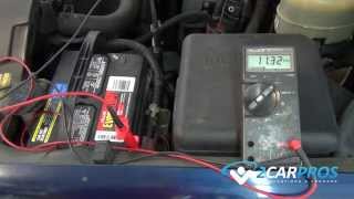
1. Disconnect the negative battery cable.
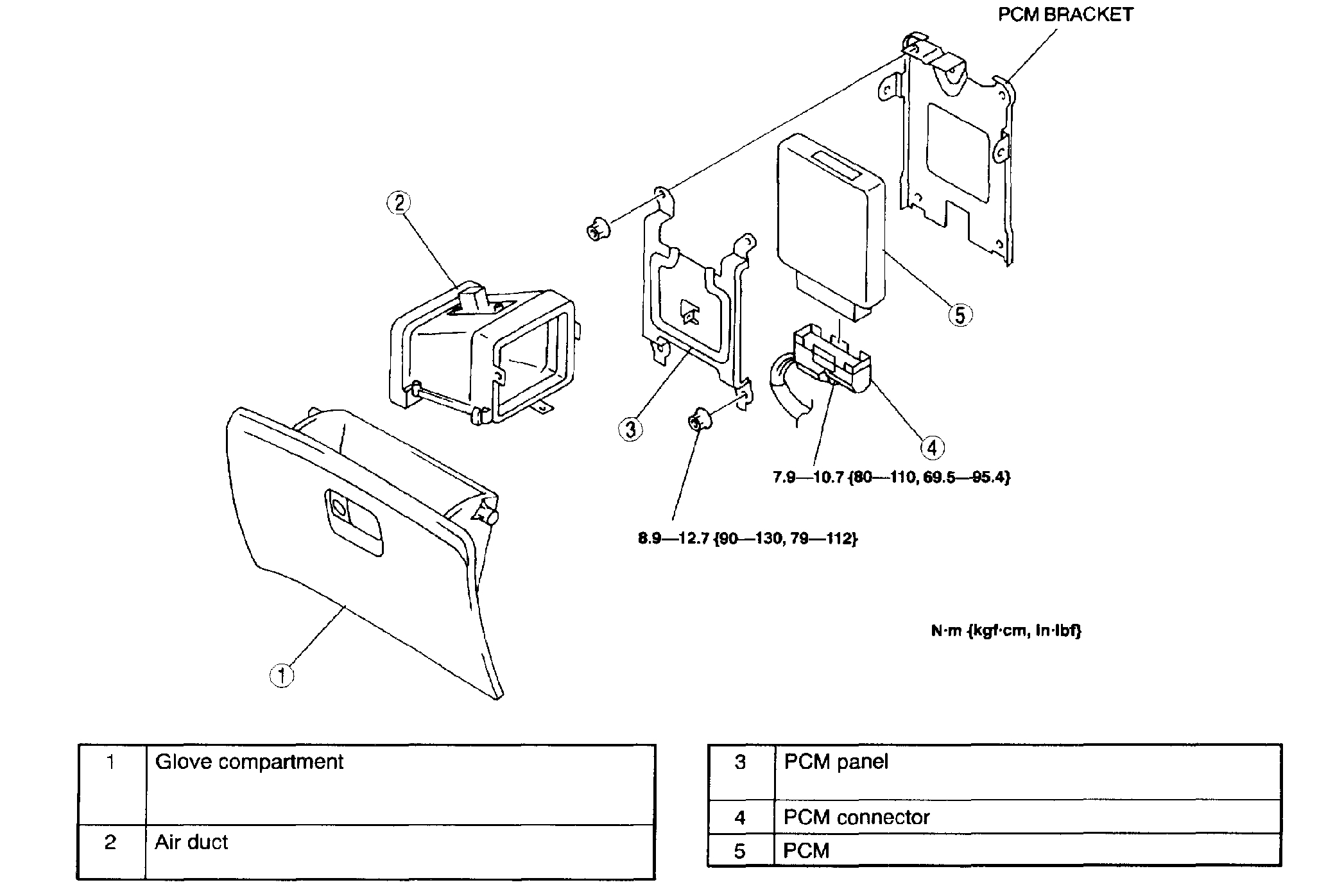
Pic 1

2. Remove in the order indicated in the table.
3. Install in the reverse order of removal.

Air Duct Removal Note
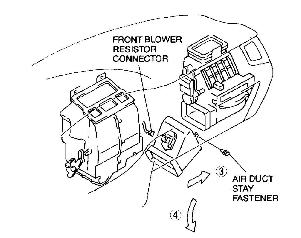
pic 2

1. Disconnect the front blower resistor connector.
2. Remove the air duct stay fastener.
3. Slide the air duct to the right.
4. Till the left side down to remove the air duct from the installation place.

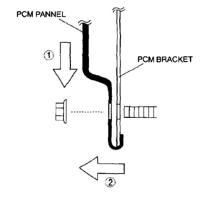
PCM Panel Removal Note
1. Before removing the PCM panel, pull the PCM connector harness stay fastener out from the PCM panel.
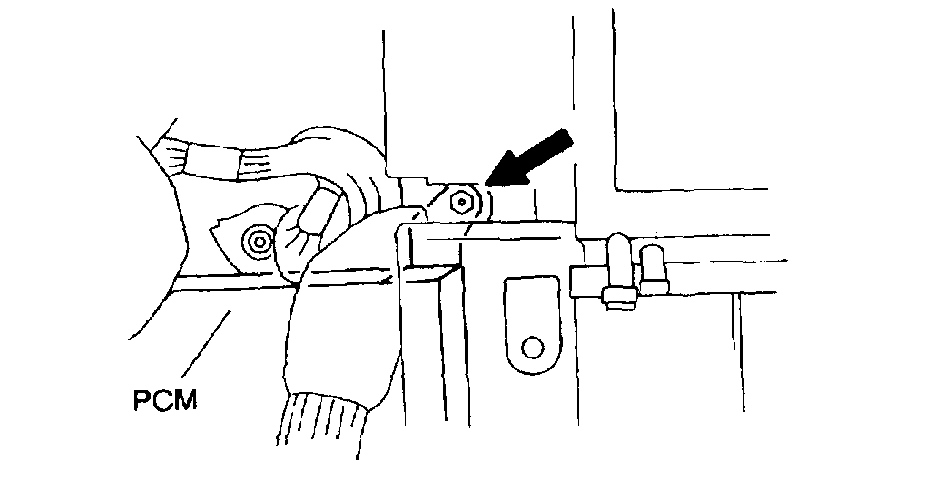
Pic 3

2. Remove the upper right side of the PCM panel installation nut located at the back of the blower unit as shown.
3. Remove the lower side of the PCM panel installation nuts located at the bottom of the cabin carpet.

Pic 4

4. Remove four installation nuts, then pull the PCM panel down to remove from installation place.

____________________________

Now, with the replacement of the PCM, the immobilizer will need reset to work with the PCM. Here are the directions for doing that.

____________________________

CODE WORD INPUT PROCEDURE
NOTE:
- A code word is composed of eight digits from 1-9 and is pant of the immobilizer unit from the manufacturer. Each unit has its own code word. To obtain the code word, you need to have the immobilizer serial number, then ask the distributor.
- To input the code word into the PCM, turn the ignition key and count the number of flashes of the security light. The calculation of the number of flashes of the security light comes with the timing of the turning of the key.

1. Wait for 5 minutes until security light flashes slowly. (300 ms ON - 300 ms OFF -> 1.2 s ON - 1.2 s OFF)

pic 5

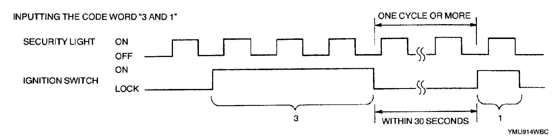
2. Input the code word as shown in the example.
1. Turn ignition switch to ON position while security light is off and count three illumination cycles. As the light goes out after the third illumination, turn key to LOCK position.
2. Wait at least one illumination cycle and within 30 seconds of going to LOCK position, turn ignition switch to ON position while security light is off and count one illumination cycle. As the light goes out after the first illumination, turn key to LOCK position.
3. Repeat Step (2) for rest of six digits.

3. When code word is registered correctly in the PCM, the security light stops flashing and illuminates.
4. As soon as the security light stops flashing and illuminates, the following immobilizer system reprogram procedure should be started.

NOTE: If the code word is not input correctly, the security light goes out after all eight digits are input. In this case, perform the "Code Word Input Error Recovery Procedure".

Examples of Incorrect Input of Code Word

NOTE:
- The security light must flash one or more times between the digits of the code word.
- If the code word is input incorrectly, the security light goes out. Turn the ignition switch to ON position then back to LOCK position five times (except PCM replacement) or six times (PCM replacement) and repeat the procedure to input all eight figures for the code word.
- When an error occurs during the reprogram procedures except when both the immobilizer unit and PCM are replaced, repeat the procedure from Step 1. If you still cannot reprogram, confirm how many keys can start the engine. Then, perform the key replacement or addition reprogram procedure according to the valid key number.
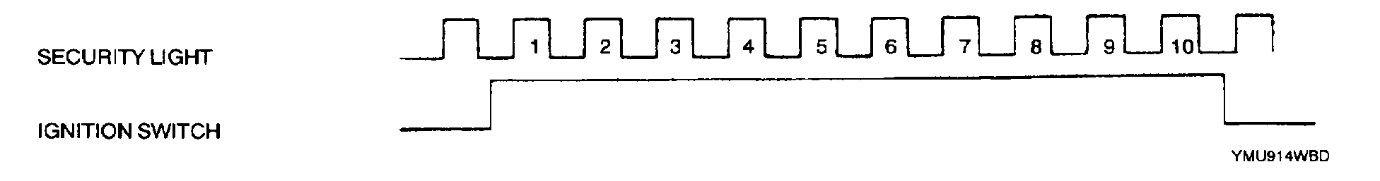
Pic 6

- The security light flashes ten or more times while the ignition switch is at ON position.

Pic 7

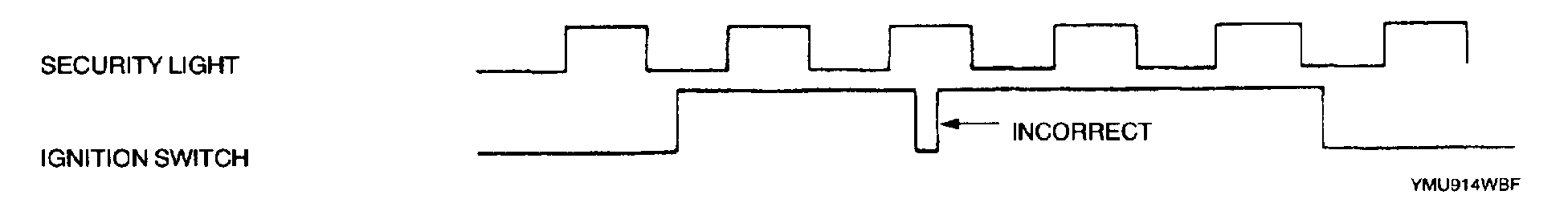
- The ignition switch is turned to ON position and LOCK position while the security light is off.

Pic 8

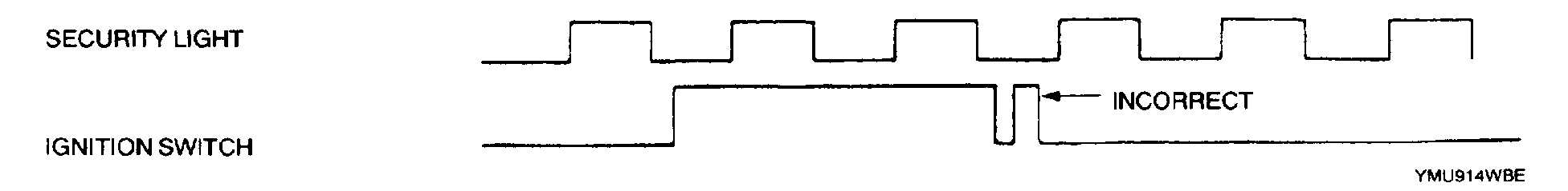
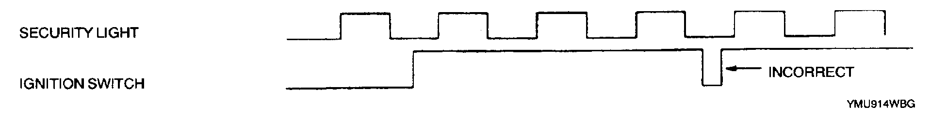
- The ignition switch is turned to LOCK position and ON position while the security light is on.

Pic 9

- The ignition switch is turned to LOCK position and ON position while the security light is off.

- The unmatching code word is input to the immobilizer unit.

Code Word Input Error Recovery Procedure
1. Turn ignition switch to ON position then back to LOCK position five times (except PCM replacement) or six times (PCM replacement). The key should not remain at ON position or LOCK position for more than 1 second.
2. Repeat the "CODE WORD INPUT PROCEDURE".

_____________________________________

Again, I figured I would add the aforementioned directions just in case you wanted to do it yourself or wanted to know what was involved. Let me know if you have questions and how things work out for you.

Take care of yourself.

Joe
Was this
answer
helpful?
Yes
No
+1
Saturday, April 20th, 2019 AT 7:09 PM

Please login or register to post a reply.

Sponsored links