Here are the directions for self testing. It includes all aspects of the security/alarm system. I'm not sure what you are exactly looking for, so let me know if this helps.
2002 Jeep Truck Liberty Sport 4WD V6-3.7L VIN K
Vehicle Theft/Security System (VTSS) Self Tests
Vehicle Accessories and Optional Equipment Antitheft and Alarm Systems Testing and Inspection Component Tests and General Diagnostics Vehicle Theft Security System (VTSS) Vehicle Theft/Security System (VTSS) Self Tests
VEHICLE THEFT/SECURITY SYSTEM (VTSS) SELF TESTS
The Vehicle Theft Security System (VTSS) is divided into two basic subsystems: Vehicle Theft Alarm (VTA) and Sentry Key Immobilizer System (SKIS). Following are the recommended procedures for diagnosis and testing of each of these two subsystems.
Warning: on vehicles equipped with airbags, disable the supplemental restraint system before attempting any steering wheel, steering column, driver airbag, passenger airbag, seat belt tensioner, front impact sensors, side curtain airbag, or instrument panel component diagnosis or service. Disconnect and isolate the battery negative (ground) cable, then wait two minutes for the system capacitor to discharge before performing further diagnosis or service. This is the only sure way to disable the supplemental restraint system. Failure to take the proper precautions could result in accidental airbag deployment and possible personal injury.
VEHICLE THEFT ALARM
Models equipped with the Rest-Of-World (ROW) premium version of the Vehicle Theft Alarm (VTA) provide some preliminary diagnostic feedback by illuminating the security indicator located in the ElectroMechanical Instrument Cluster (EMIC). If the security indicator illuminates with the ignition switch in the On position, it indicates that there is a communication problem between the Intrusion Transceiver Module (ITM) and the Body Control Module (BCM), or between the ITM and the siren module. The BCM will also turn on the security indicator if it receives a message from the ITM indicating that the ITM has stored a Diagnostic Trouble Code (DTC) for a siren module fault.
The hard wired circuits and components of the VTA may be diagnosed and tested using conventional diagnostic tools and procedures. However, conventional diagnostic methods may not prove conclusive in the diagnosis of the Body Control Module (BCM), the ElectroMechanical Instrument Cluster (EMIC), the Intrusion Transceiver Module (ITM), or the Programmable Communications Interface (PCI) data bus network. The most reliable, efficient, and accurate means to diagnose the BCM, the EMIC, the ITM, and the PCI data bus network inputs and outputs related to the VTA requires the use of a DRBIII scan tool. Refer to the appropriate diagnostic information.
Refer to the appropriate wiring information. The wiring information includes wiring diagrams, proper wire and connector repair procedures, further details on wire harness routing and retention, as well as pin-out and location views for the various wire harness connectors, splices and grounds.
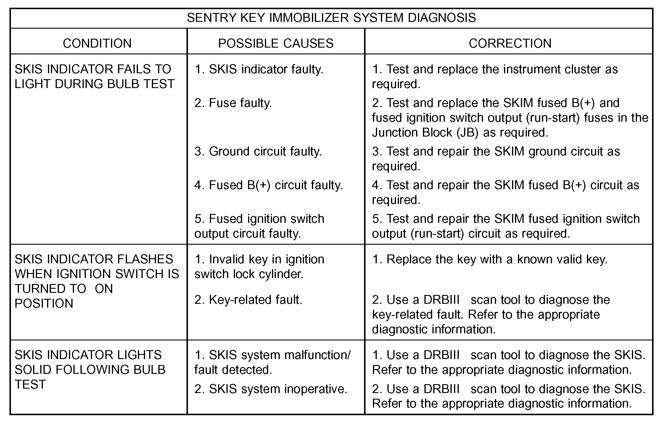
Sentry Key Immobilizer System Diagnosis
pic 1
SENTRY KEY IMMOBILIZER SYSTEM
SKIS Indicator Fails To Light During Bulb Test
If the Sentry Key Immobilizer System (SKIS) indicator in the instrument cluster fails to illuminate for about three seconds after the ignition switch is turned to the ON position (bulb test), perform the instrument cluster actuator test. (Refer to INSTRUMENT CLUSTER - DIAGNOSIS AND TESTING). If the SKIS indicator still fails to light during the bulb test, a wiring problem resulting in the loss of battery current or ground to the Sentry Key Immobilizer Module (SKIM) should be suspected, and the following procedure should be used for diagnosis. Refer to the appropriate wiring information. The wiring information includes wiring diagrams, proper wire and connector repair procedures, details of wire harness routing and retention, connector pin-out information and location views for the various wire harness connectors, splices and grounds.
NOTE: The following tests may not prove conclusive in the diagnosis of this system. The most reliable, efficient, and accurate means to diagnose the Sentry Key Immobilizer System requires the use of a DRBIII scan tool. Refer to the appropriate diagnostic information.
1. Check the fused B(+) fuse (Fuse 33 - 10 ampere) in the Junction Block (JB). If OK, go to Step 2. If not OK, repair the shorted circuit or component as required and replace the faulty fuse.
2. Check for battery voltage at the fused B(+) fuse (Fuse 33 - 10 ampere) in the JB. If OK, go to Step 3. If not OK, repair the open B(+) circuit between the JB and the battery as required.
3. Check the fused ignition switch output (run- start) fuse (Fuse 15 - 10 ampere) in the JB. If OK, go to Step 4. If not OK, repair the shorted circuit or component as required and replace the faulty fuse.
4. Turn the ignition switch to the ON position. Check for battery voltage at the fused ignition switch output (run-start) fuse (Fuse 15 - 10 ampere) in the JB. If OK, go to Step 5. If not OK, repair the open fused ignition switch output (run-start) circuit between the JB and the ignition switch as required.
5. Disconnect and isolate the battery negative cable. Disconnect the instrument panel wire harness connector for the Sentry Key Immobilizer Module (SKIM) from the SKIM connector receptacle. Check for continuity between each of the two ground circuit cavities of the instrument panel wire harness connector for the SKIM and a good ground. There should be continuity. If OK, go to Step 6. If not OK, repair the open ground circuit(s) to ground (G202) as required.
6. Reconnect the battery negative cable. Check for battery voltage at the fused B(+) circuit cavity of the instrument panel wire harness connector for the SKIM. If OK, go to Step 7. If not OK, repair the open fused B(+) circuit between the SKIM and the JB as required.
7. Turn the ignition switch to the ON position. Check for battery voltage at the fused ignition switch output (run-start) circuit cavity of the instrument panel wire harness connector for the SKIM. If OK, use a DRBIII scan tool to complete the diagnosis of the SKIS. Refer to the appropriate diagnostic information. If not OK, repair the open fused ignition switch output (run-start) circuit between the SKIM and the JB as required.
SKIS Indicator Flashes Upon Ignition "ON" Or Lights Solid Following Bulb Test
A SKIS indicator that flashes following the ignition switch being turned to the ON position indicates that an invalid key has been detected, or that a key-related fault has been set. A SKIS indicator that lights solid following a successful bulb test indicates that the SKIM has detected a system malfunction or that the SKIS is inoperative. In either case, fault information will be stored in the SKIM memory. For retrieval of this fault information and further diagnosis of the SKIS, the PCI data bus, the SKIM electronic message outputs to the instrument cluster that control the SKIS indicator and chime, or the electronic message inputs and outputs between the SKIM and the Powertrain Control Module (PCM) that control engine operation, a DRBIII scan tool is required. Refer to the appropriate diagnostic information.
Following are preliminary troubleshooting guidelines to be followed during diagnosis using a DRBIII scan tool:
1. Using the DRBIII scan tool, read and record the faults as they exist in the SKIM when you first begin your diagnosis of the vehicle. It is important to document these faults because the SKIM does not differentiate between historical faults (those that have occurred in the past) and active faults (those that are currently present). If this problem turns out to be an intermittent condition, this information may become invaluable to your diagnosis.
2. Using the DRBIII scan tool, erase all of the faults from the SKIM.
3. Cycle the ignition switch to the OFF position, then back to the ON position.
4. Using the DRBIII scan tool, read any faults that are now present in the SKIM. These are the active faults.
5. Using this active fault information, refer to the proper procedure in the appropriate diagnostic information for the specific additional diagnostic steps.
______________________________
Let me know if you have other questions.
Take care,
Joe
Image (Click to make bigger)
SPONSORED LINKS
Sunday, March 8th, 2020 AT 7:42 PM