Hello, I'm Tom and can give you a hand.
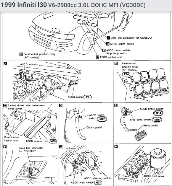
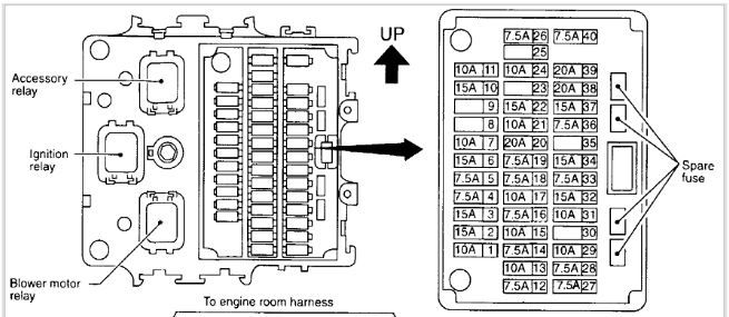
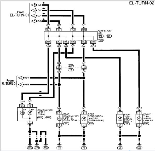
First thing you want to do is check the 2 fuses relating to that circuit which is #11 and #14. They are probably good but check the turn signal switch is a combination switch along with the hazard switch. If its not the flasher it will be the turn signal itself. How did the problem arise, It just stopped? Nothing like the turn signal arm got hit or anything like that? Check and feel the movement of the arm masking sure its tight and not loose in its proper movements. Your going to want to get to the wire leaving the flasher. Test it with a test light, check the signal leaving the switch. Use the chart below for your colors. Below I have a location diagram
The description of operation is as follows:
With the hazard switch in the "off" position and the ignition switch in the "on" or "start" position, power is supplied
through 7.5 A fuse [No. (1), located in the fuse block (J/B)]
to hazard switch terminal (2)
through terminal (1) of the hazard switch
to combination flasher unit terminal (1)
through terminal (3) of the combination flasher unit
to turn signal switch terminal (1).
Ground is supplied to combination flasher unit terminal (2) through body grounds (M13), (M73) and (M103).
LH turn
When the turn signal switch is moved to the LH position, power is supplied from turn signal switch terminal (3) to
front turn signal lamp LH terminal (1) [through fuse block (J/B) terminals (5S) and (6S)]
rear combination lamp LH terminal (2) [through fuse block (J/B) terminals (5S) and (4Q)] and
combination meter terminal(23) [through fuse block (J/B) terminals (5S) and (12J)].
Ground is supplied to the front turn signal lamp LH terminal (2) through body grounds (E5) and (E30).
Ground is supplied to the rear combination lamp LH terminal (4) through body grounds (T6) and (T9).
Ground is supplied to combination meter terminal (7) through body grounds (M13), (M73) and (M103).
With power and grounds supplied, the combination flasher unit controls the flashing interval of the LH turn signal lamps.
RH turn
When the turn signal switch is moved to the RH position, power is supplied from turn signal switch terminal (2) to
front turn signal lamp RH terminal (1) [through fuse block (J/B) terminals (14S) and (10S)]
rear combination lamp RH terminal (2) [through fuse block (J/B) terminals (14S) and (13Q)] and
combination meter terminal (22) [through fuse block (J/B) terminals (14S) and (5H)].
Ground is supplied to the front turn signal lamp RH terminal (2) through body grounds (E5) and (E30).
Ground is supplied to the rear combination lamp RH terminal (4) through body grounds (T6) and (T9).
Ground is supplied to combination meter terminal (7) through body grounds (M13), (M73) and (M103).
With power and ground supplied, the combination flasher unit controls the flashing interval of the RH turn signal lamps.
If you have any more question about this let me know
Tom
Images (Click to make bigger)
SPONSORED LINKS
Friday, August 7th, 2020 AT 8:13 PM