Hi,
If it only the one side, there is 1. The replacement process is somewhat involved. Here are the directions. The attached pics correlate with the directions.
_____________________________
2006 Hyundai Elantra L4-2.0L
Front Hub & Knuckle
Vehicle Steering and Suspension Wheels and Tires Wheel Hub Service and Repair Procedures Front Hub & Knuckle
FRONT HUB & KNUCKLE
pic 1
REMOVAL
1. Remove the front wheel and tire.
2. Remove the split pin, then remove castle nut and washer from the front hub under applying the brake.
Pic 2
pic 3
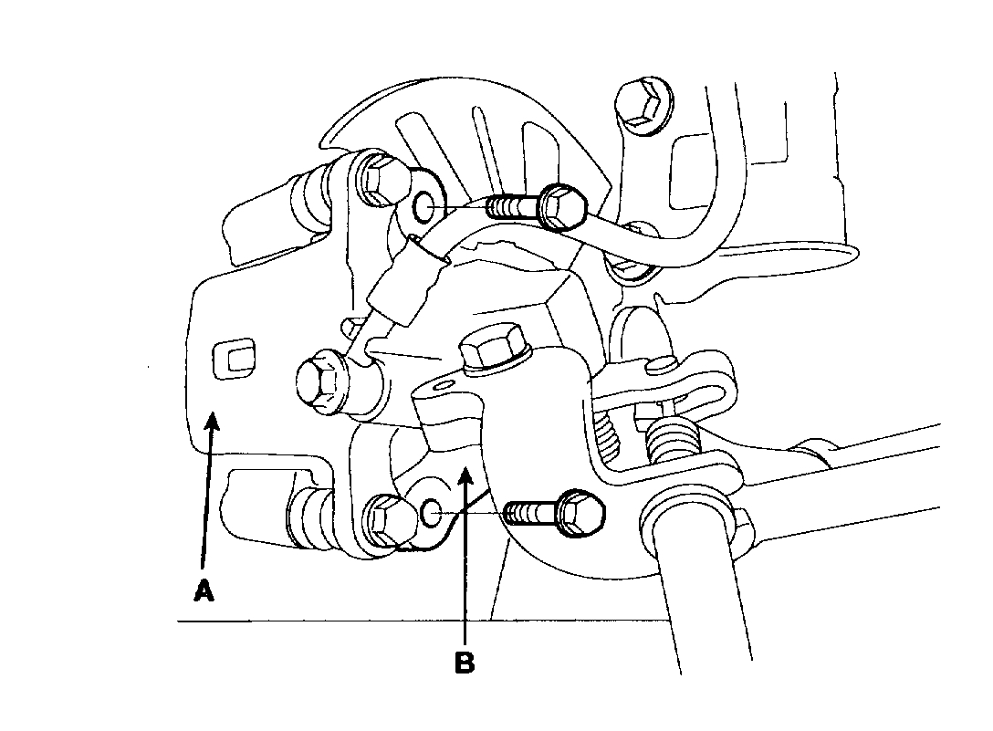
3. Remove the caliper(A) from the knuckle(B) and hang the caliper(A) on the front damper(C) with wire(D).
Pic 4
4. Remove the wheel speed sensor(A) from the knuckle(B).
Pic 5
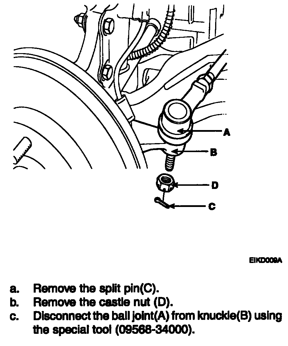
5. Disconnect the tie rod end ball joint(A) from the knuckle(B) using the special tool(09568-34000).
CAUTION: Be sure to tie the special tool (09568-34000) to the near part with cord not to fall.
Pic 6
6. Disconnect the strut assembly from the knuckle.
7. Disconnect the driveshaft from the hub.
8. Remove the hub and knuckle as an assembly.
CAUTION: Be careful not to damage the boot and tone wheel.
DISASSEMBLY
pic 7
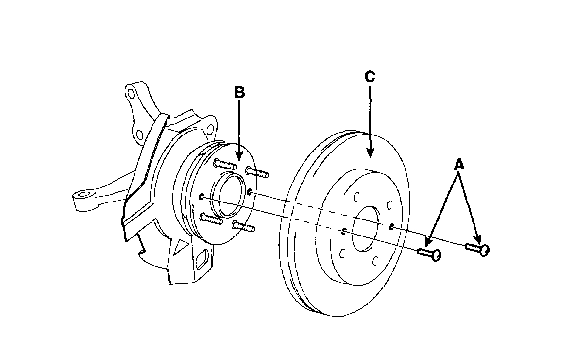
1. After removing the fixed screws(A) mounting the brake disc(C), remove the brake disc(C) from the hub(B).
Pic 8
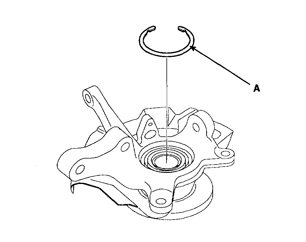
2. Remove the snap ring(A).
Pic 9
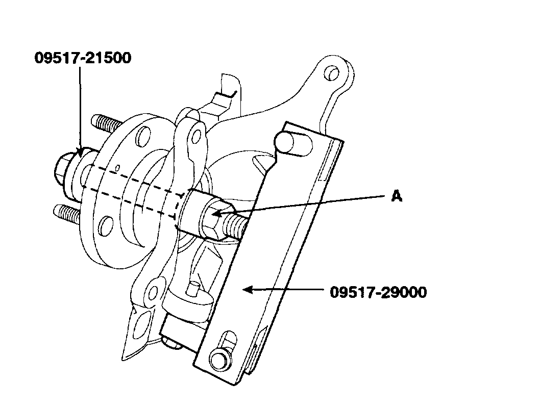
3. Install the special tools (09517-29000, 09517-21500) as shown in illustration.
4. Separate the hub from the knuckle by turning nut(A) of the special tool (09517-21500).
5. Remove the special tools (09517-21500, 09517-29000) and dust cover.
Pic 10
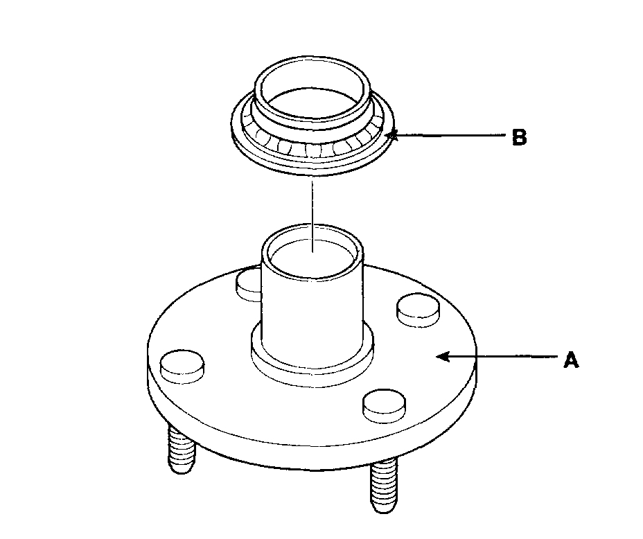
6. Remove the bearing inner race(B) from the hub(A) using the special tool (09495-33000).
Pic 11
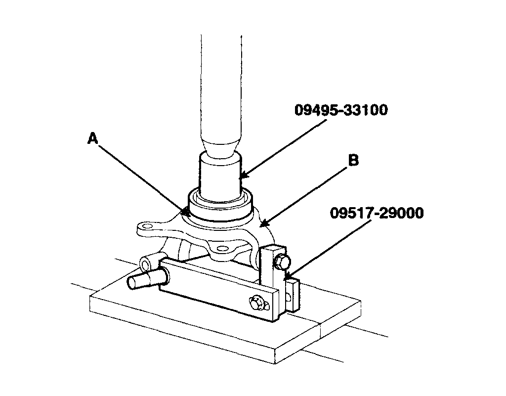
7. Using the special tools (09495-33100, 09517-29000), remove the wheel bearing outer race(A) from the knuckle(B).
8. Using a plastic hammer, remove the dust cover from the knuckle.
INSPECTION
Wheel Bearing Check
pic 12
1. Raise the vehicle until the front tires are off the floor.
Make sure the wheels are in a straight forward position.
Pic 13
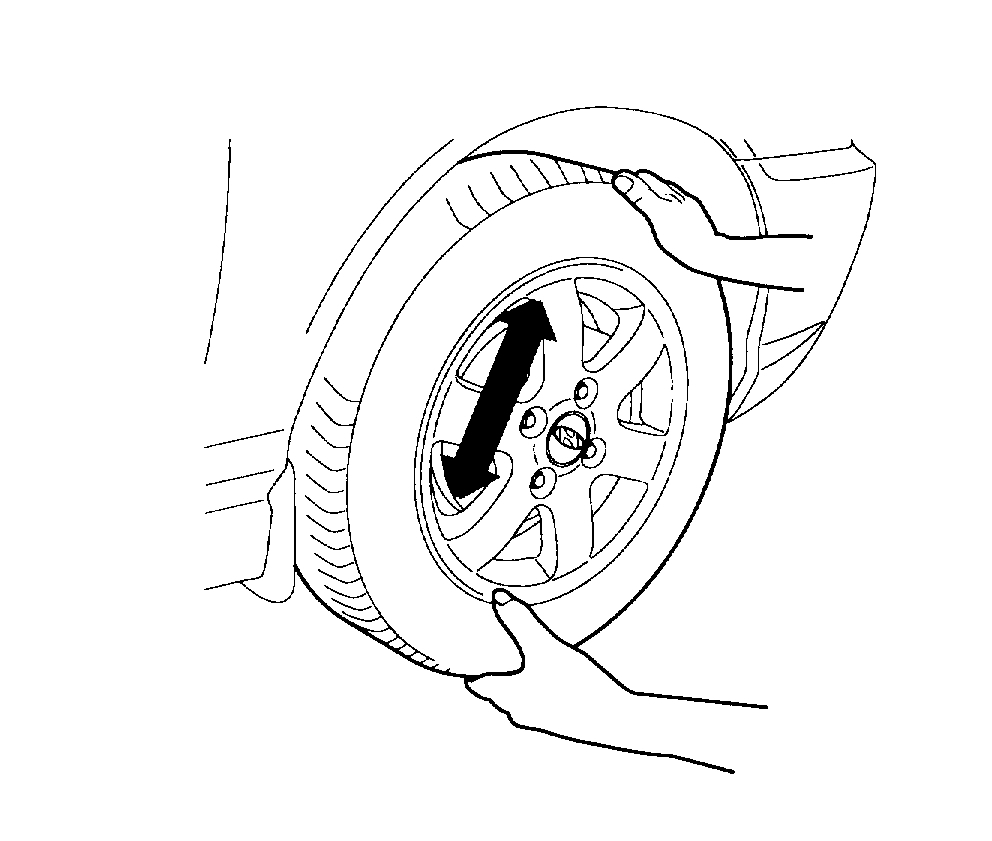
2. Grip each front tire at the top and bottom, and move the wheel inward and outward while lifting the weight of the tire off the front wheel bearings.
3. If the tire and wheel (hub) is loose on the spindle, does not rotate freely, or has a rough feeling when spun, carry out one of the following.
On vehicles with inner and outer bearings, inspect the bearings and races for wear or damage. Adjust or install new bearing and races as necessary.
4. Check the hub for cracks and the splines for wear.
5. Check the brake disc for scoring and damage.
6. Check the knuckle for cracks.
7. Check the bearing for cracks or damage.
REASSEMBLY
1. Apply multi-purpose grease to the contacting surface of the knuckle hub and bearing thinly.
Pic 14
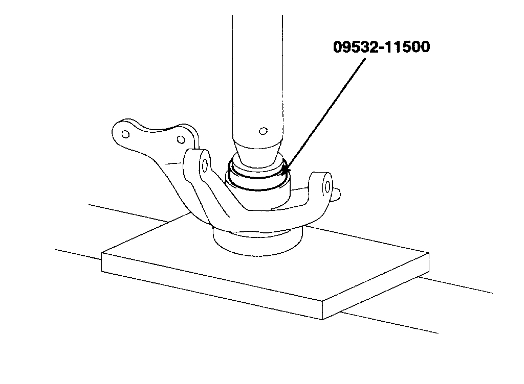
2. Using the Special Tool (09532-11500), press-in the bearing to the knuckle.
NOTE:
Press-in the outer race of the wheel bearing to prevent damage to the bearing assembly.
When installing a bearing assembly, always use a new one.
The right and the left bearing must be made in the same company.
3. Using a plastic hammer, install the snap ring and dust cover.
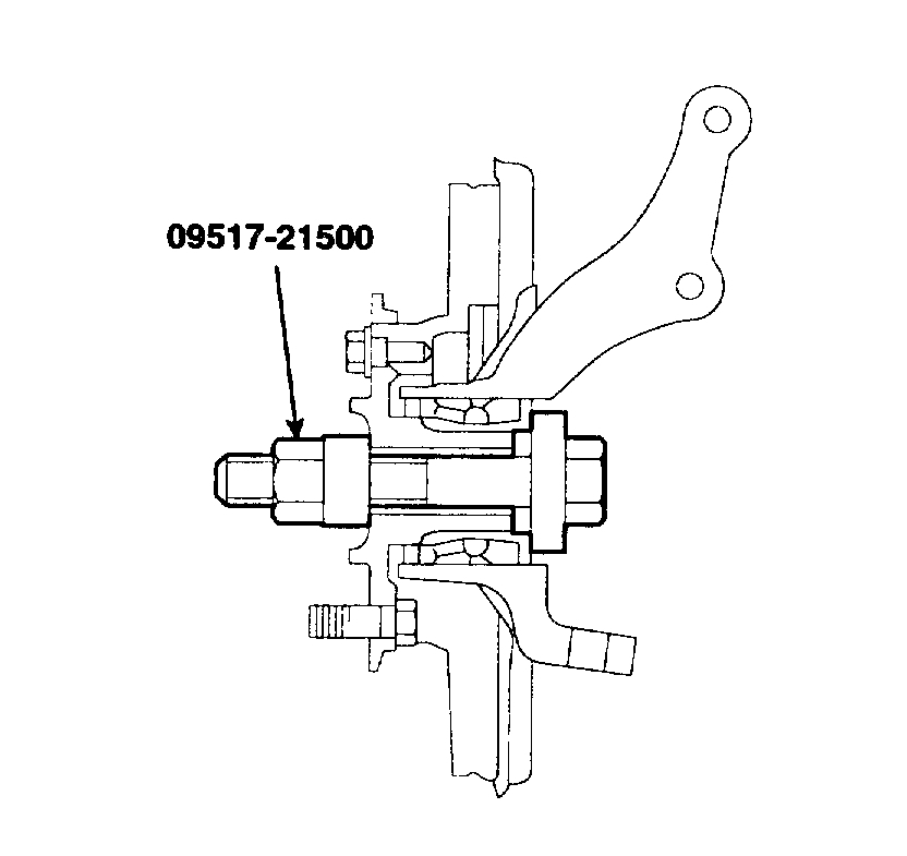
4. Using the Special Tool (09517-21500), press-in the hub to the knuckle.
NOTE: Press-in the inner race of the wheel bearing to prevent damage to the bearing assembly.
5. Install the brake disc.
Pic 15
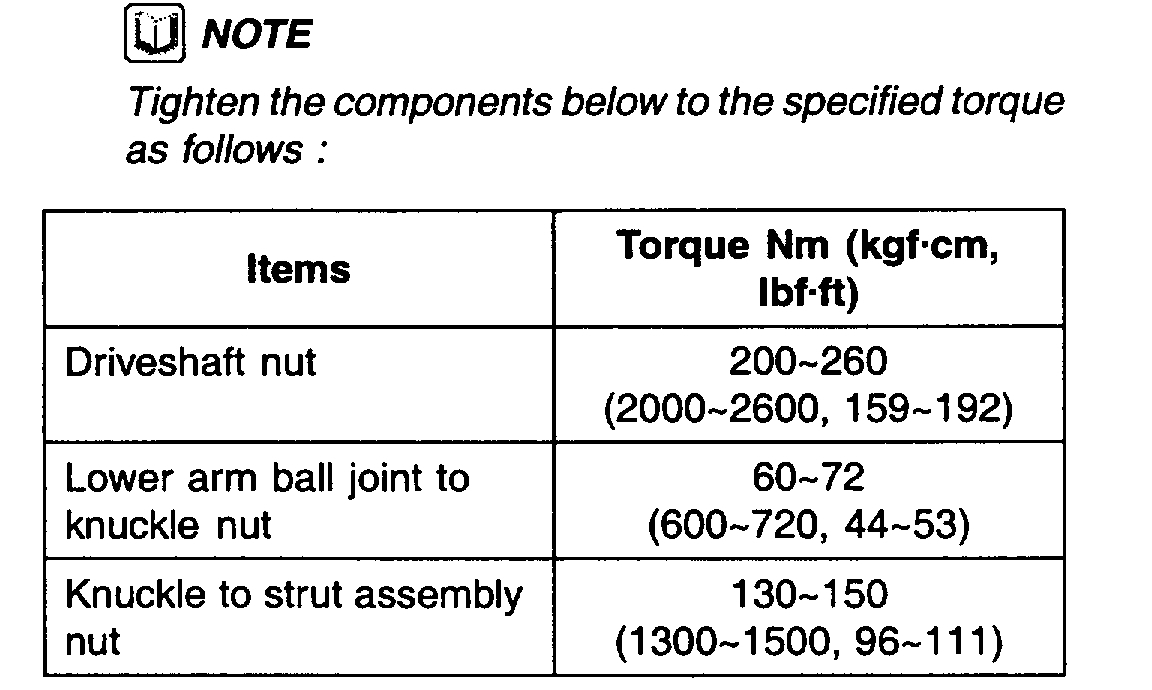
6. Tighten the hub and the knuckle to the specified torque using the Special Tool (09517-21500).
Specified torque Nm (kgf-cm, ft. Lbs.) 200 - 260 (2000 - 2600, 159 - 192)
pic 16
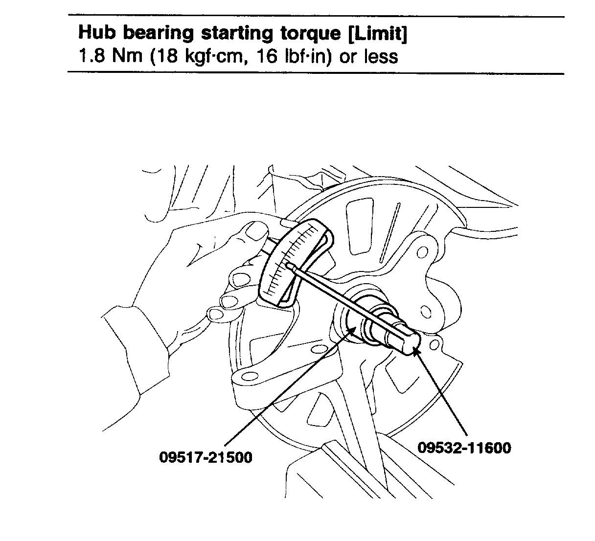
7. Measure the hub bearing starting torque.
Hub bearing starting torque [Limit 1.8 Nm (18 kgf-cm, 16 inch lbs.) Or less
pic 17
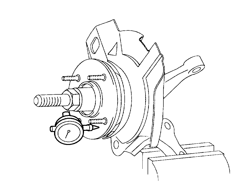
8. If the starting torque is 0 Ncm (0 inch lbs.), Measure the hub bearing axial play.
9. If the hub axial play exceeds the limit while the nut is tightened to 200 - 260 Nm (2000 - 2600 kgf-cm, 159 - 192 ft. Lbs.), The bearing, hub and knuckle are not installed correctly. Repeat the disassembly and assembly procedure.
Hub bearing axial play [Limit] 0.008 mm (0.0003 inch) or less
10. Remove the Special Tool.
11. Fix the brake disc with the mounting screws.
INSTALLATION
1. Installation is the reverse of the removal procedures.
Pic 18
2. Install the strut assembly and the driveshaft in the knuckle.
3. Connect the wheel speed sensor.
4. Install the caliper assembly in the hub and knuckle assembly which the brake disc is already installed.
5. Tighten the lower arm ball joint nut.
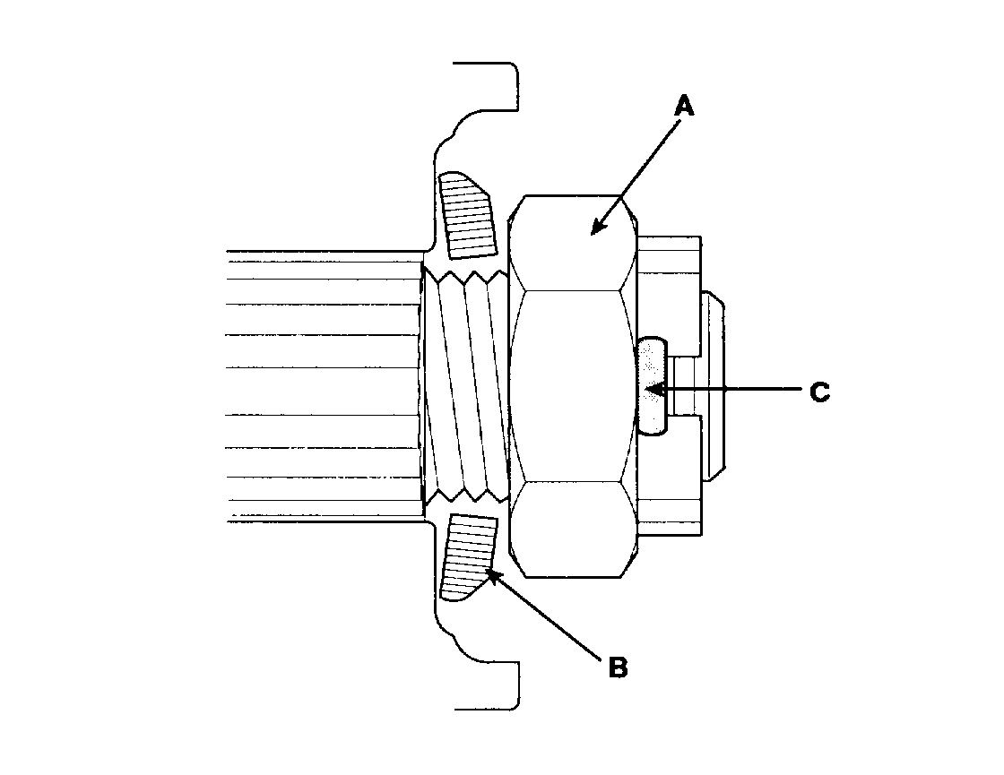
6. Tighten the tie rod end ball joint nut and insert the split pin(C).
7. Insert the washer(B) and tighten the castle nut(A).
Pic 19
8. Insert the split pin(C).
_____________________________________
Let me know if this helps or if you have other questions.
Take care,
Joe
Images (Click to make bigger)
SPONSORED LINKS
Monday, January 6th, 2020 AT 9:07 PM