It looks to me like they're still using the older, easy-to-diagnose-circuit. The first diagram is the aftermarket version of the charging system, but to help explain it, they left out a few details. I added them in the second diagram. In older models, the 12 volt supply was switched on through the automatic shutdown (ASD) relay that also powered up the injectors and ignition coil(s). Here they show it coming directly from fuse M28 in the under-hood fuse box. I'd like you to tell me if you have that 12 volts on the back of the alternator all the time, just when the ignition switch is in "run", or only when the engine is running. On older models it was just when the engine was running. We'll get to that shortly.
In the second diagram, I used arrows to show the current path to make the electromagnetic field in the alternator. Where I put the red arrowed line, there is actually a hard-wired connection inside the Engine Computer. Current flows through the computer, then through the spinning field coil and a pair of brushes to make the contacts. It leaves the alternator and continues back to the computer where it flows through the voltage regulator circuitry, then to ground. If anything interrupts that current path, no electromagnetic field will be developed, and the alternator will stop working. By far the most common cause of that, especially at higher mileages, is worn brushes. Those always start out as an intermittent no-charge condition that gets worse and worse over months, Those brushes can be replaced separately for about ten dollars.
The next suspect would be a break in the brown / dark green wire going to the computer. Far down on the list of suspects would be the voltage regulator circuitry. That causes relatively little trouble.
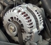
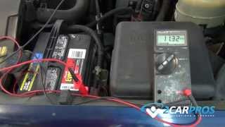
The place to start is by measuring the three voltages on the back of the alternator. To be valid, that must be done with the engine running. There must always be full system voltage on the large bolted on output wire. The other two are usually two very small nuts holding two tabs coming out of a black plastic block. On newer models they changed that to a pair of wires in a small two-wire plug. That way you can tell which wire is which. One of them must have full system voltage, (12 volts or a little more). If that is missing, check the fuse. The key is the other small terminal. That one must have less than 12 volts, but not 0 volts. You'll typically find between 4 - 11 volts. The lower that voltage is, the higher the difference is between the two, and the stronger magnetic field that is being developed, and therefore, more output current.
You're going to find one of three conditions on that second wire. If you find less voltage on the brown / dark green wire than on the gray / red wire, that half of the alternator is working properly. If you find 0 volts, the brushes are worn. Either replace them, or most people just replace the entire alternator. If you find exactly the same voltage on both smaller wires, typically just under 12.6 volts, there's a break in the circuit after the alternator, starting with that brown / dark green wire. There's usually a connector in that wire, but these aftermarket diagrams often don't show them. That's a good place to find corroded terminals. This can also be caused by a defective voltage regulator circuit inside the computer.
When you do find the same voltage on both smaller wires, we'd like to verify the alternator itself is okay when we put a repair estimate together. To do that, ground the brown / dark green wire. That will make the alternator charge wide open. To be safe, don't raise engine speed during the few seconds it takes to perform this test. If the head lights are on, they'll get brighter. You'll hear the alternator whine, and it will drag engine speed down a little.
For the benefit of others researching this topic, when you have the same voltage on both wires, and they travel through that black plastic block I mentioned, there's no way to know which color wire goes to which terminal. If you do the test and ground the wrong wire, you'll blow the fuse. On older models from the '90s, you will likely burn out the connection in the computer. There's an easy way to figure out which terminal to ground. It can't be done with a voltmeter, and it can't be done with a test light. It IS easy to figure out when using both at the same time. I can elaborate on that if it becomes necessary.
When you have the regular two-wire connector, you can see which wire is which, so figuring out which one to ground is simply a matter of looking at them.
When you find the correct 4 - 11 volts on the brown / dark green wire, that only means the input section is working. The alternator can still be defective if there's a defect in the output section. I can elaborate on that too, but it doesn't apply here to the problem we're trying to solve.
Let me know what you find with these three voltages, then, if Ken doesn't see your reply first, I'll continue on.
Images (Click to make bigger)
Monday, April 22nd, 2024 AT 7:31 PM