Here are the complete removal and installation guide.
TIMING CHAIN & SPROCKETS
REMOVAL
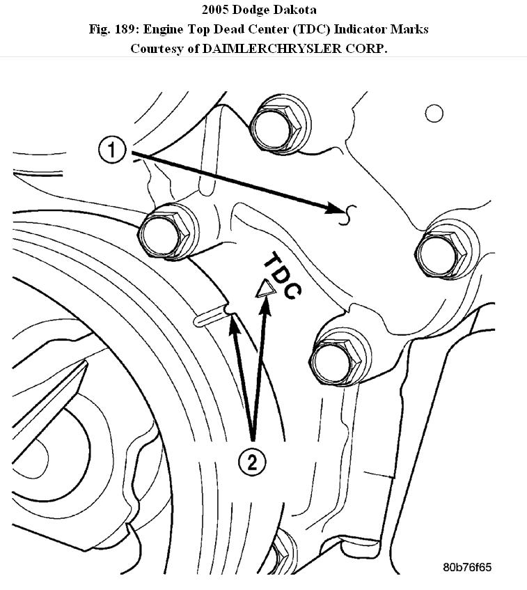
Fig. 189: Engine Top Dead Center (TDC) Indicator Marks
Courtesy of DAIMLERCHRYSLER CORP.
1 - TIMING CHAIN COVER
2 - CRANKSHAFT TIMING MARKS
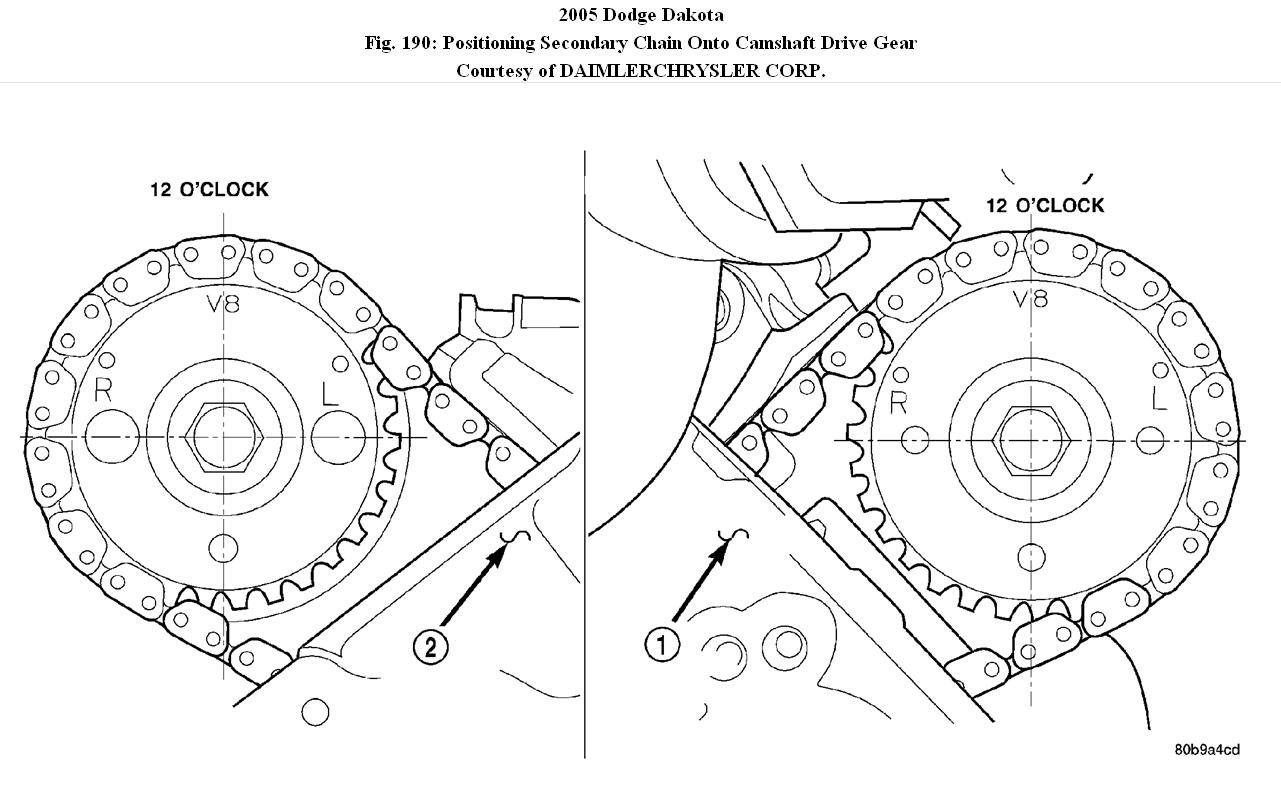
Fig. 190: Positioning Secondary Chain Onto Camshaft Drive Gear
Courtesy of DAIMLERCHRYSLER CORP.
1 - LEFT CYLINDER HEAD
2 - RIGHT CYLINDER HEAD
1. Disconnect negative cable from battery.
2. Drain cooling system
3. Remove right and left cylinder head covers.
4. Remove radiator fan shroud.
5. Rotate engine until timing mark (2) on crankshaft damper aligns with TDC mark on timing chain cover (2) (#1 cylinder exhaust stroke) and the camshaft sprocket "V8" marks are at the 12 o'clock position (1, 2).
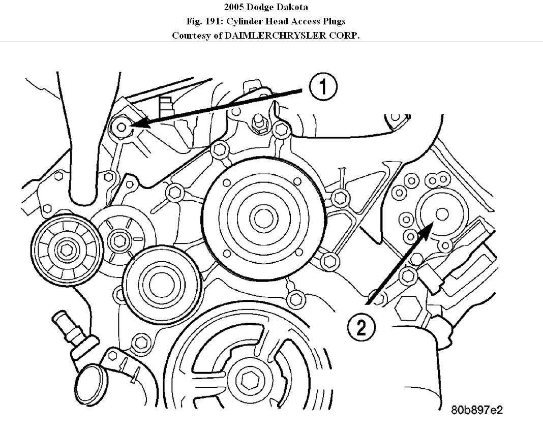
Fig. 191: Cylinder Head Access Plugs
Courtesy of DAIMLERCHRYSLER CORP.
1 - RIGHT CYLINDER HEAD ACCESS PLUG
2 - LEFT CYLINDER HEAD ACCESS PLUG
6. Remove power steering pump.
7. Remove access plugs (1, 2) from left and right cylinder heads for access to chain guide fasteners.
8. Remove the oil fill housing to gain access to the right side tensioner arm fastener.
9. Remove crankshaft damper and timing chain cover.
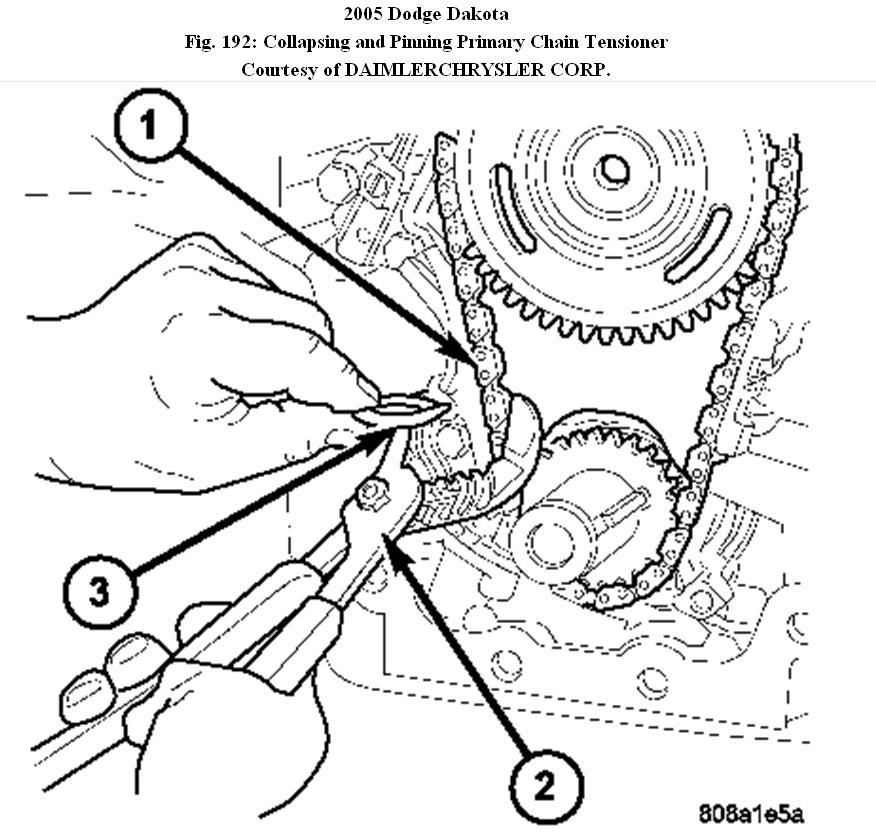
Fig. 192: Collapsing and Pinning Primary Chain Tensioner
Courtesy of DAIMLERCHRYSLER CORP.
1 - PRIMARY CHAIN TENSIONER
2 - ADJUSTABLE PLIERS
3 - SPECIAL TOOL 8514
10. Collapse and pin primary chain tensioner (1).
CAUTION:Plate behind left secondary chain tensioner could fall into oil pan. Therefore, cover pan opening.
11. Remove secondary chain tensioners.
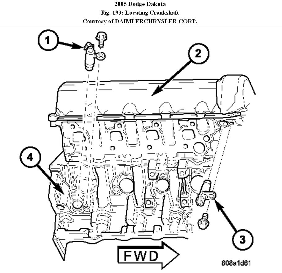
Fig. 193: Locating Crankshaft & Camshaft Position Sensors
Courtesy of DAIMLERCHRYSLER CORP.
1 - CRANKSHAFT POSITION SENSOR
2 - CYLINDER HEAD COVER
3 - CAMSHAFT POSITION SENSOR
4 - RIGHT SIDE CYLINDER BLOCK
12. Remove camshaft position sensor (1) from right cylinder head.
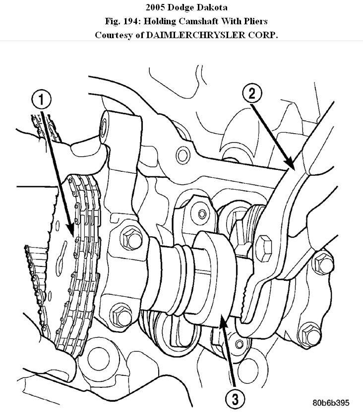
Fig. 194: Holding Camshaft With Pliers
Courtesy of DAIMLERCHRYSLER CORP.
1 - CAMSHAFT SPROCKET AND CHAIN
2 - ADJUSTABLE PLIERS
3 - CAMSHAFT
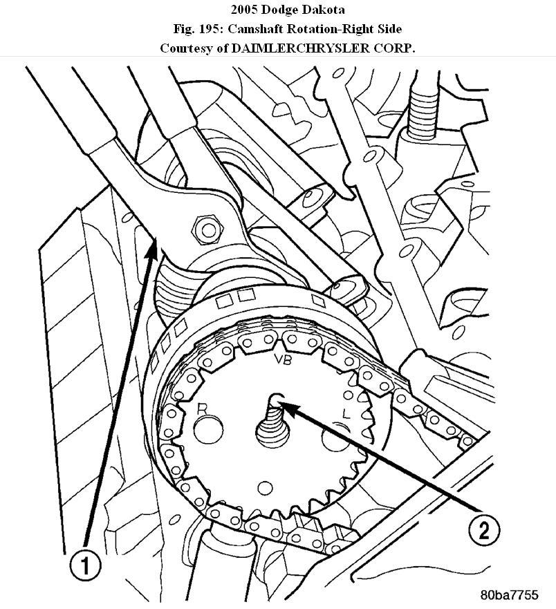
Fig. 195: Camshaft Rotation-Right Side
Courtesy of DAIMLERCHRYSLER CORP.
1 - ADJUSTABLE PLIERS
2 - CAMSHAFT DOWEL
CAUTION:Care should be taken not to damage camshaft target wheel. Do not hold target wheel while loosening or tightening camshaft sprocket. Do not place the target wheel near a magnetic source of any kind. A damaged or magnetized target wheel could cause a vehicle no start condition.
CAUTION:Do not forcefully rotate the camshafts or crankshaft independently of each other. Damaging intake valve to piston contact will occur. Ensure negative battery cable is disconnected to guard against accidental starter engagement.
13. Remove left and right camshaft sprocket bolts.
14. While holding the left camshaft steel tube with adjustable pliers (1), remove the left camshaft sprocket. Slowly rotate the camshaft approximately 15 degrees clockwise to a neutral position.
15. While holding the right camshaft steel tube with adjustable pliers (1), remove the right camshaft sprocket. Slowly rotate the camshaft approximately 45 degrees counterclockwise to a neutral position.
16. Remove idler sprocket assembly bolt.
17. Slide the idler sprocket assembly and crank sprocket forward simultaneously to remove the primary and secondary chains.
18. Remove both pivoting tensioner arms and chain guides.
19. Remove chain tensioner.
INSPECTION
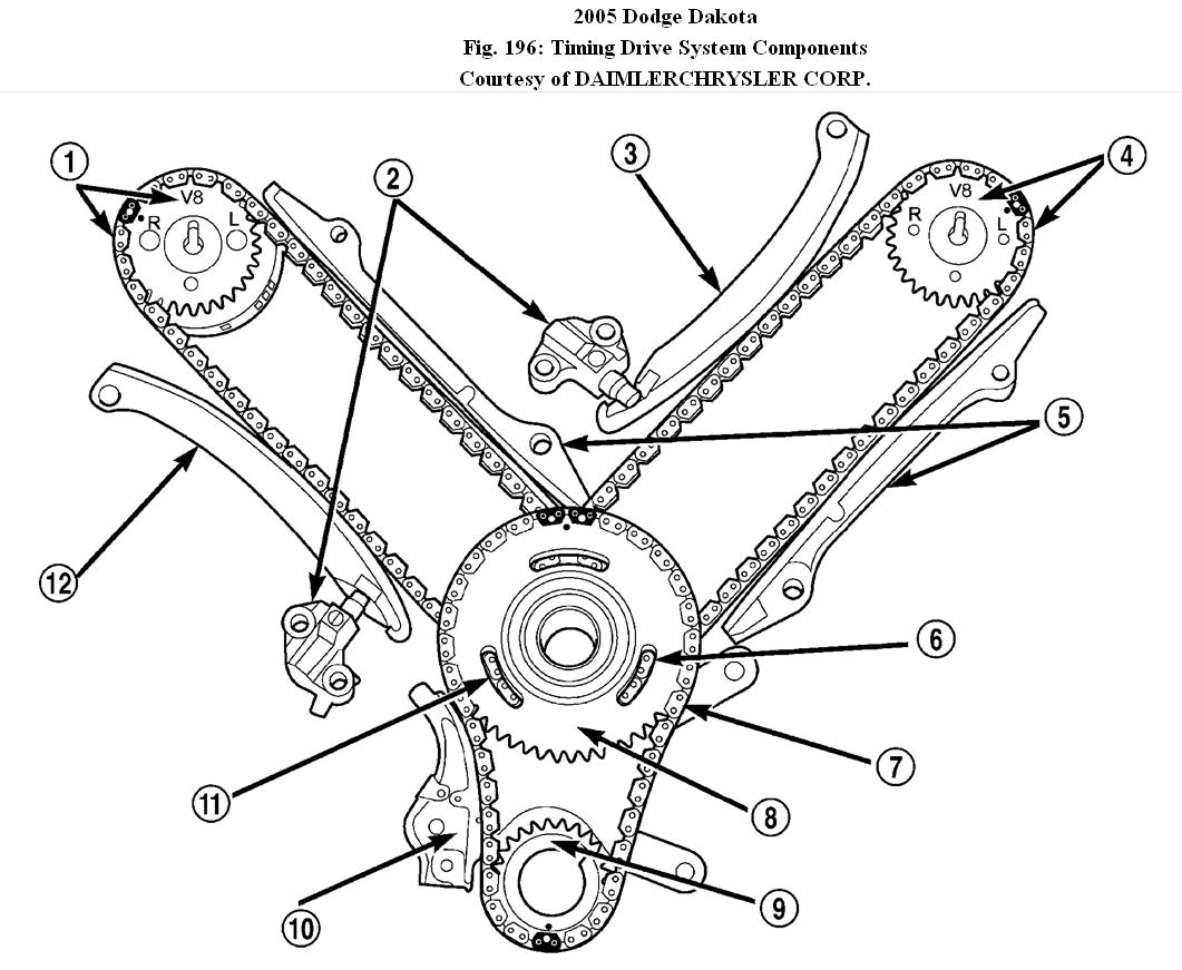
Fig. 196: Timing Drive System Components
Courtesy of DAIMLERCHRYSLER CORP.
1 - RIGHT CAMSHAFT SPROCKET AND SECONDARY CHAIN
2 - SECONDARY TIMING CHAIN TENSIONER (LEFT AND RIGHT SIDE NOT COMMON)
3 - SECONDARY TENSIONER ARM
4 - LEFT CAMSHAFT SPROCKET AND SECONDARY CHAIN
5 - CHAIN GUIDE
6 - TWO PLATED LINKS ON RIGHT CAMSHAFT CHAIN
7 - PRIMARY CHAIN
8 - IDLER SPROCKET
9 - CRANKSHAFT SPROCKET
10 - PRIMARY CHAIN TENSIONER
11 - TWO PLATED LINKS ON LEFT CAMSHAFT CHAIN
12 - SECONDARY TENSIONER ARM
Inspect the following components:
� Sprockets for excessive tooth wear. Some tooth markings are normal and not a cause for sprocket replacement.
� Idler sprocket assembly bushing and shaft for excessive wear.
� Idler sprocket assembly spline joint. The joint should be tight with no backlash or axial movement.
� Chain guides and tensioner arms. Replace these parts if grooving in plastic face is more than 1 mm (0.039 in.) Deep. If plastic face is severely grooved or melted, the tensioner lube jet may be clogged. The tensioner should be replaced.
� Secondary chain tensioner piston and ratcheting device. Inspect for evidence of heavy contact between tensioner piston and tensioner arm. If this condition exist the tensioner and tensioner arm should be replaced.
� Primary chain tensioner plastic faces. Replace as required.
INSTALLATION
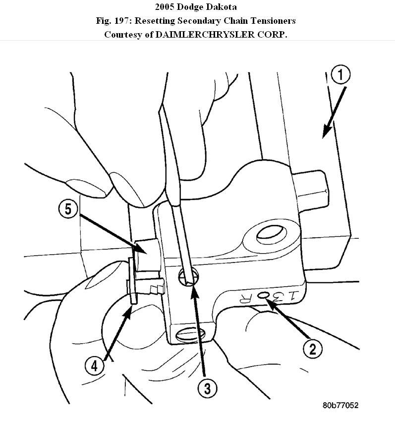
Fig. 197: Resetting Secondary Chain Tensioners
Courtesy of DAIMLERCHRYSLER CORP.
1 - VISE
2 - TENSIONER BODY
3 - INSERT LOCK PIN
4 - RATCHET
5 - PISTON
1. Using a vise, lightly compress the secondary chain tensioner piston until the piston step is flush with the tensioner body. Using a pin or suitable tool, release ratchet pawl by pulling pawl back against spring force through access hole on side of tensioner. While continuing to hold pawl back, Push ratchet device to approximately 2 mm from the tensioner body. Install Special Tool 8514 lock pin (3) into hole on front of tensioner (2). Slowly open vise to transfer piston spring force to lock pin.
2. Position primary chain tensioner over oil pump and insert bolts into lower two holes on tensioner bracket. Tighten bolts to 28 N.M (250 in. Lbs.).
CAUTION: Overtightening the tensioner arm Torx� bolt can cause severe damage to the cylinder head. Tighten Torx� bolt to specified torque only.
3. Install right side chain tensioner arm. Apply Mopar� Lock N, Seal to Torx� bolt, tighten bolt to 17 N.M (150 in. Lbs.).
NOTE: The silver bolts retain the guides to the cylinder heads and the
black bolts retain the guides to the engine block.
4. Install the left side chain guide. Tighten the bolts to 28 N.M (250 in. Lbs.).
CAUTION:Overtightening the tensioner arm Torx� bolt can cause severe
damage to the cylinder head. Tighten Torx� bolt to specified torque only.
5. Install left side chain tensioner arm. Apply Mopar� Lock N, Seal to Torx� bolt, tighten bolt to 17 N.M (150 in. Lbs.).
6. Install the right side chain guide. Tighten the bolts to 28 N.M (250 in. Lbs.).
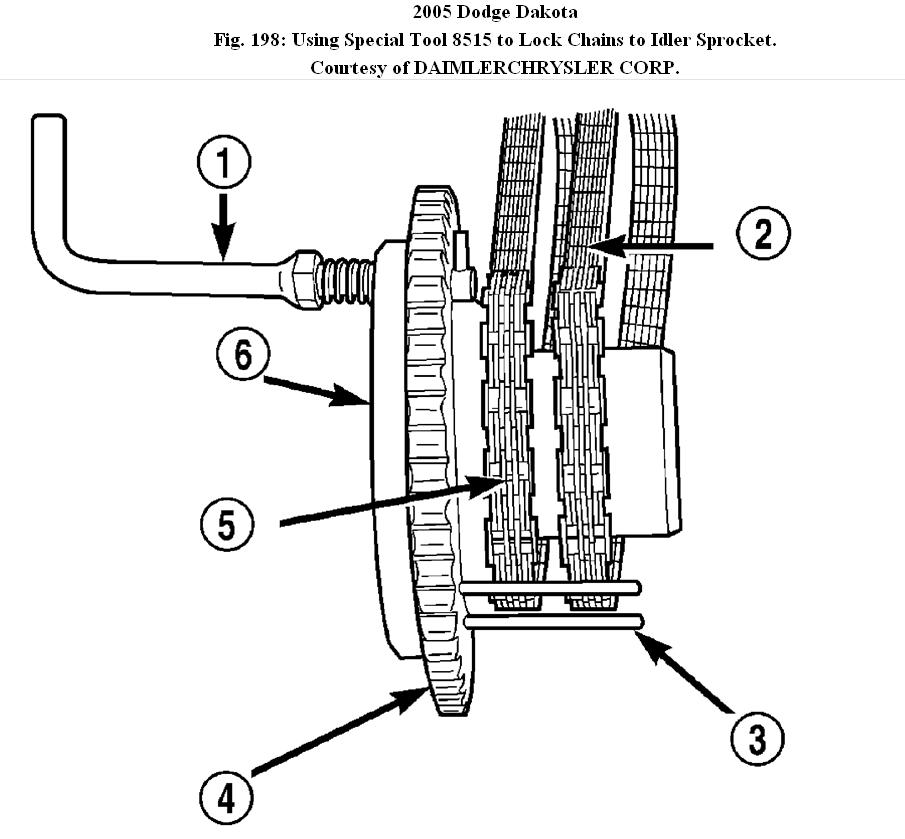
Fig. 198: Using Special Tool 8515 to Lock Chains to Idler Sprocket.
Courtesy of DAIMLERCHRYSLER CORP.
1 - LOCK ARM
2 - RIGHT CAMSHAFT CHAIN
3 - SECONDARY CHAINS RETAINING PINS (4)
4 - IDLER SPROCKET
5 - LEFT CAMSHAFT CHAIN
6 - SPECIAL TOOL 8515
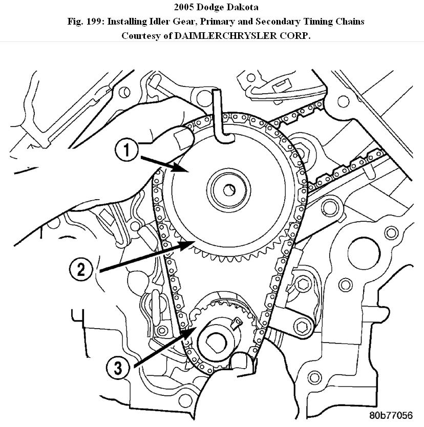
Fig. 199: Installing Idler Gear, Primary and Secondary Timing Chains
Courtesy of DAIMLERCHRYSLER CORP.
1 - SPECIAL TOOL 8429
2 - PRIMARY CHAIN IDLER SPROCKET
3 - CRANKSHAFT SPROCKET
7. Install both secondary chains onto the idler sprocket. Align two plated links on the secondary chains to be visible through the two lower openings on the idler sprocket (4 o'clock and 8 o'clock). Once the secondary timing chains are installed, position special tool 8515 (6) to hold chains in place for installation.
8. Align primary chain double plated links with the timing mark at 12 o'clock (1) on the idler sprocket. Align the primary chain single plated link with the timing mark at 6 o'clock on the crankshaft sprocket (3).
9. Lubricate idler shaft and bushings with clean engine oil.
10. Install all chains, crankshaft sprocket, and idler sprocket as an assembly. After guiding both secondary chains through the block and cylinder head openings, affix chains with a elastic strap or the equivalent, This will maintain tension on chains to aid in installation.
NOTE: It will be necessary to slightly rotate camshafts for sprocket
installation.
11. Align left camshaft sprocket "L" dot to plated link on chain.
12. Align right camshaft sprocket "R" dot to plated link on chain.
CAUTION:Remove excess oil from the camshaft sprocket bolt. Failure to do so can result in over-torque of bolt resulting in bolt failure.
13. Remove Special Tool 8515, then attach both sprockets to camshafts. Remove excess oil from bolts, then Install sprocket bolts, but do not tighten at this time.
14. Verify that all plated links are aligned with the marks on all sprockets and the "V8" marks on camshaft sprockets are at the 12 o'clock position. See Fig. 196.
CAUTION:Ensure the plate between the left secondary chain tensioner and block is correctly installed.
15. Install both secondary chain tensioners. Tighten bolts to 28 N.M (250 in. Lbs.).
NOTE: Left and right secondary chain tensioners are not common.
16. Before installing idler sprocket bolt, lubricate washer with oil, and tighten idler sprocket assembly retaining bolt to 34 N.M (25 ft. Lbs.).
17. Remove all locking pins (3) from tensioners.
CAUTION:After pulling locking pins out of each tensioner, DO NOT manually extend the tensioner(s) ratchet. Doing so will over tension the chains, resulting in noise and/or high timing chain loads.
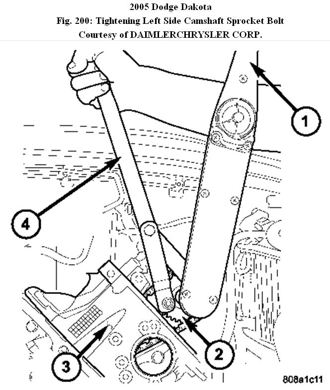
Fig. 200: Tightening Left Side Camshaft Sprocket Bolt
Courtesy of DAIMLERCHRYSLER CORP.
1 - TORQUE WRENCH
2 - CAMSHAFT SPROCKET
3 - LEFT CYLINDER HEAD
4 - SPECIAL TOOL 6958 SPANNER WITH ADAPTER PINS 8346
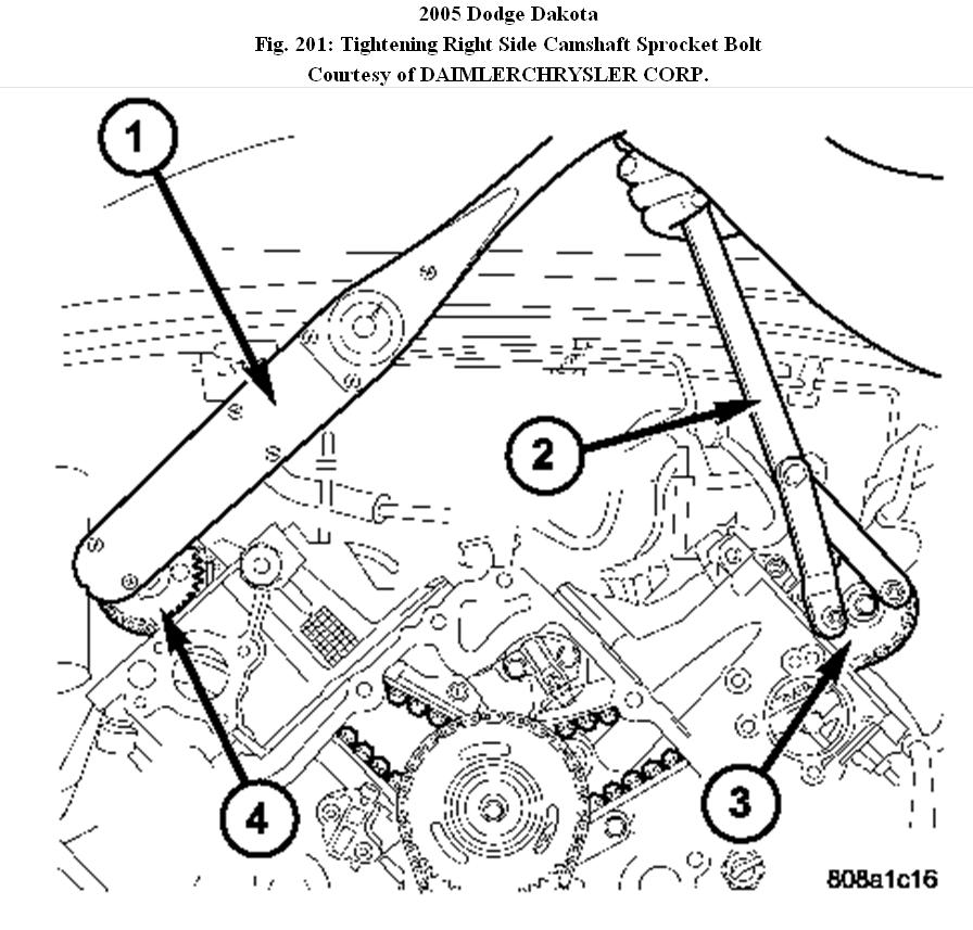
Fig. 201: Tightening Right Side Camshaft Sprocket Bolt
Courtesy of DAIMLERCHRYSLER CORP.
1 - TORQUE WRENCH
2 - SPECIAL TOOL 6958 WITH ADAPTER PINS 8346
3 - LEFT CAMSHAFT SPROCKET
4 - RIGHT CAMSHAFT SPROCKET
18. Using Special Tool 6958, Spanner with Adaptor Pins 8346, tighten left (3) and right (4),
camshaft sprocket bolts to 122 N.M (90 ft. Lbs.).
19. Rotate engine two full revolutions. Verify timing marks are at the follow locations:
� primary chain idler sprocket dot is at 12 o'clock
� primary chain crankshaft sprocket dot is at 6 o'clock
� secondary chain camshaft sprockets "V8" marks are at 12 o'clock
20. Lubricate all three chains with engine oil.
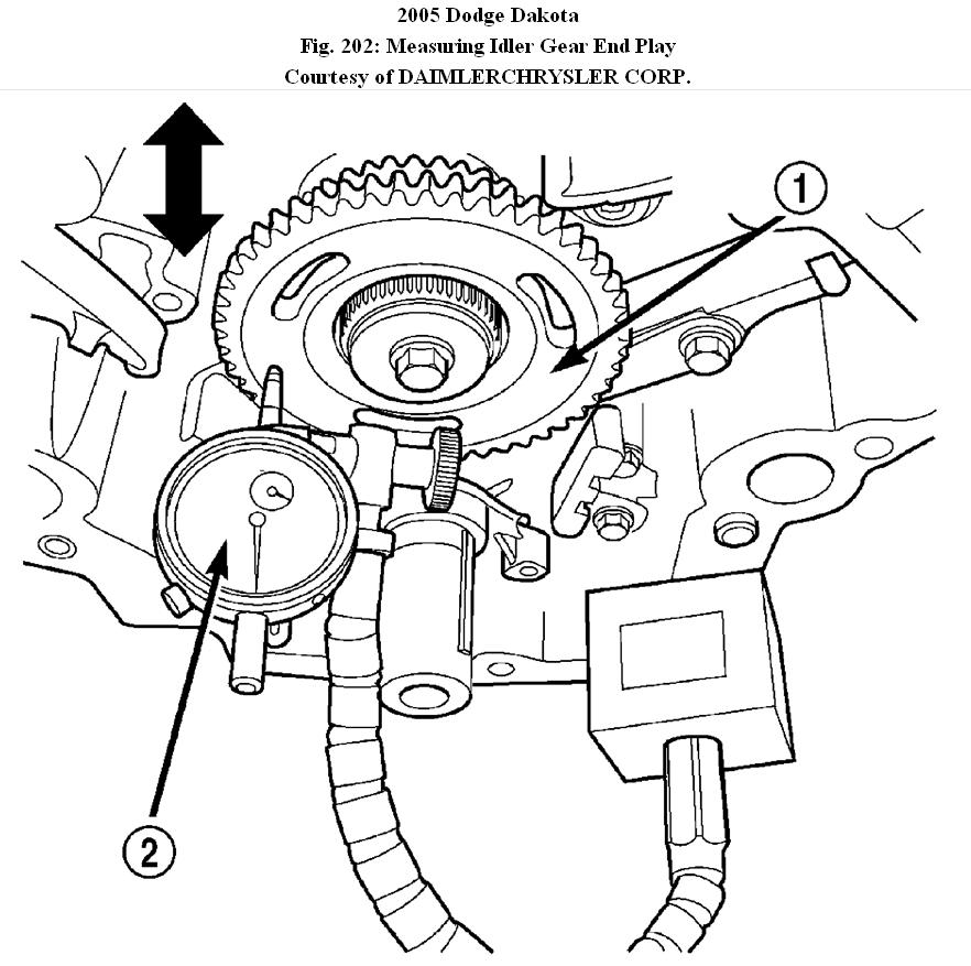
Fig. 202: Measuring Idler Gear End Play
Courtesy of DAIMLERCHRYSLER CORP.
1 - IDLER SPROCKET ASSEMBLY
2 - DIAL INDICATOR
21. After installing all chains, it is recommended that the idler gear (1) end play be checked. The end play must be within 0.10-0.25 mm (0.004-0.010 in.). If not within specification, the idler gear must be replaced.
22. Install timing chain cover and crankshaft damper.
23. Install cylinder head covers
NOTE: Before installing threaded plug in right cylinder head, the plug
must be coated with sealant to prevent leaks.
24. Coat the large threaded access plug with Mopar� Thread Sealant with Teflon, then install into the right cylinder head and tighten to 81 N.M (60 ft. Lbs.). See Fig. 191.
25. Install the oil fill housing.
26. Install access plug in left cylinder head. See Fig. 191.
27. Install power steering pump
28. Install radiator fan shroud.
29. Fill cooling system
30. Connect negative cable to battery.
Images (Click to make bigger)
Sunday, December 5th, 2010 AT 12:42 PM