DTC P1250: PRC SOLENOID VALVE CIRCUIT MALFUNCTION
Detection Condition
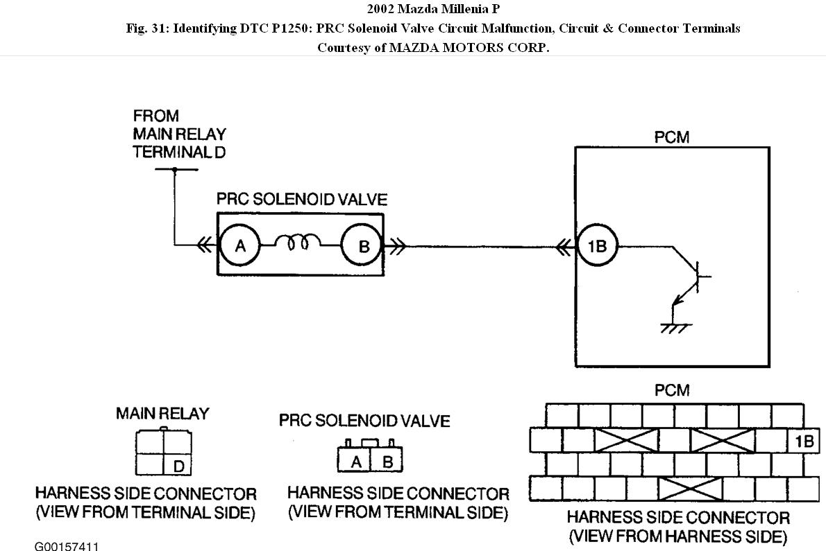
PCM monitors input voltages from PRC solenoid valve just after ignition key is turned to "ON". If voltage at PCM terminal "1B" is low. see Fig. 31, PCM determines that PRC solenoid valve circuit has a malfunction.
Diagnostic Support Note
• This is a diagnostic support DTC (monitored once per key cycle).
• MIL does not illuminate.
• DTC is available if PCM detects the listed malfunction condition in two consecutive drive cycles.
• FFD is not available.
• DTC is stored in PCM
Possible Cause
• PRC solenoid valve malfunction.
• Connector or terminal malfunction.
• Short to ground in wiring between PRC solenoid valve terminal "B" and PCM terminal "1B".
• Open circuit in wiring between main relay terminal "D" and PRC solenoid valve terminal "A".
• Open circuit in wiring between PRC solenoid valve terminal "B" and PCM terminal "1B".
• PCM malfunction.
Diagnosis & Repair Procedure
1. Verify related repair information is available. Check for related service bulletins and/or on-line repair information availability. If information is available, perform repair or diagnosis according to repair information, if vehicle is not repaired, then go to next step. If information is not available, and vehicle is not repaired, then go to next step.
2. Classify intermittent or continuous concern. Turn ignition key to "ON" (engine "OFF"). If the same DTC is present, go to next step. If the same DTC is not present, an intermittent concern exists.
3. Classify open circuit or short to ground malfunction. Disconnect PRC solenoid valve tube that connects to the intake manifold. Connect a vacuum pump to PRC solenoid valve. Apply vacuum and wait 5 seconds. If vacuum is maintained, go to step 5. If vacuum is not maintained, go to next step.
4. Inspect passage control of PRC solenoid valve. Turn ignition key to "OFF". Disconnect PRC solenoid valve connector. If vacuum is maintained repair or replace shorted harness between PCM terminal "1B" and PRC solenoid valve terminal "B", then go to step 10. If vacuum is not maintained, replace PRC solenoid valve, then go to step 10.
5. Inspect poor connection of PRC solenoid valve connector. Turn ignition key to "OFF". Check for poor connection (damaged, pulled-out terminals, corrosion, etc.). If a poor connection exists, repair or replace terminal, then go to step 10. If a poor connection does not exist, go to next step.
6. Inspect PRC solenoid valve. Measure resistance between PRC solenoid valve terminals (valve side). If resistance is 22-26 ohms, go to next step. If resistance is not between 22-26 ohms, replace PRC solenoid valve, then go to step 10.
7. Inspect PRC solenoid valve power supply circuit for an open. Turn ignition key to "ON" (engine "OFF"). Measure voltage between PRC solenoid valve terminal "A" (harness side) and body ground. If battery voltage exists, go to next step. If battery voltage does not exist, repair or replace open harness, then go to step 10.
8. Inspect poor connection of PCM connector. Turn ignition key to "OFF". Disconnect PCM connector. Check for poor connection at terminal "1B" (damaged, pulled-out terminal, corrosion, etc.). If a poor connection exists, repair terminal, then go to step 10. If a poor
connection does not exist, go to next step.
9. Inspect PRC solenoid valve control circuit for an open. Connect PRC control solenoid valve connector. Turn ignition key to "ON" (engine "OFF"). Measure voltage between PCM terminal "1B" and body ground. If battery voltage exists, go to next step. If battery voltage does not exist, repair or replace open harness, then go to next step.
10. Verify trouble shooting. Ensure to reconnect all disconnected connectors. Turn ignition key to "OFF" then "ON" (engine "OFF"). If the same DTC is present, replace PCM, then go to next step. If the same DTC is not present, go to next step.
11. Perform after repair procedure. If there are any DTCs present, go to applicable DTC inspection. If there are no DTCs present, trouble shooting is complete.
© 2008 Mitchell Repair Information Co., LLC.
DTC P1521: VARIABLE RESONANCE INDUCTION SYSTEM (VRIS) SOLENOID VALVE NO. 1 CIRCUIT MALFUNCTION
Detection Condition
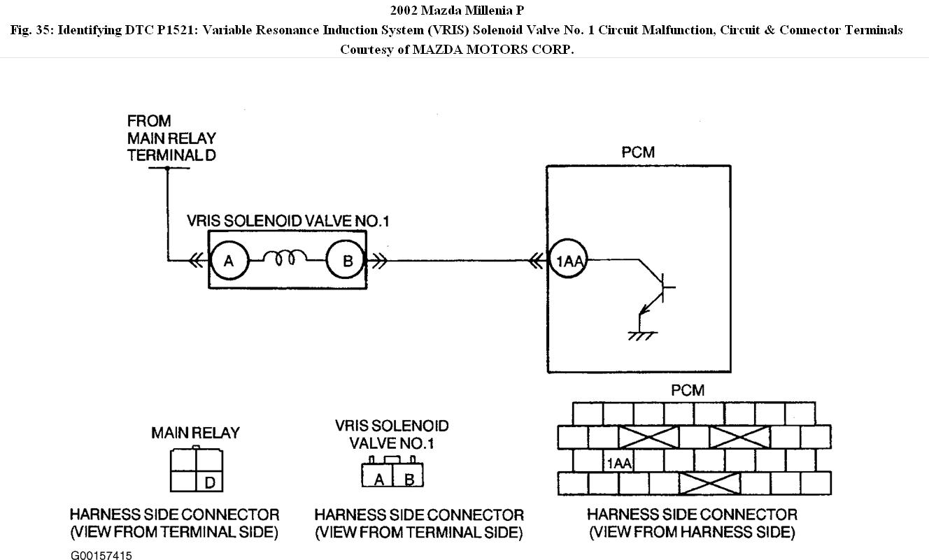
PCM monitors voltages from VRIS solenoid No. 1 just after turning the ignition key to "ON". If voltage at PCM terminal "1AA" is low PCM determines that VRIS solenoid valve No. 1 circuit has a malfunction. See Fig. 35.
Diagnostic Support Note
• This is a continuous monitor (CCM).
• MIL does not illuminate.
• FFD is not available.
• DTC is stored in PCM memory.
Possible Cause
• VRIS solenoid valve No. 1 malfunction.
• Connector or terminal malfunction.
• Short to ground in wiring between VRIS solenoid valve No. 1 terminal "B" and PCM terminal "1AA".
• Open circuit in wiring between main relay terminal "D" and VRIS solenoid valve No. 1 terminal "A".
• Open circuit in wiring between VRIS solenoid valve No.1 terminal "B" and PCM terminal "1AA".
• PCM malfunction.
Diagnosis & Repair Procedure
1. Ensure FFD has been recorded. If FFD has been recorded, go to next step. If FFD has not been recorded, record FFD on repair order, then go to next step.
2. Verify related repair information is available. Check for related service bulletins and/or on-line repair information availability. If information is available, perform repair or diagnosis according to repair information, if vehicle is not repaired, go to next step. If information is not available, and vehicle is not repaired, go to next step.
3. Classify open circuit or short to ground malfunction. Disconnect VRIS solenoid valve No. 1 tube that connects to vacuum chamber. Connect vacuum pump to VRIS solenoid valve No. 1. Apply vacuum and wait 5 seconds. If vacuum is maintained, go to step 5. If vacuum is
not maintained, go to next step.
4. Inspect passage control (PRC) of VRIS solenoid valve No. 1. Turn ignition key to "OFF". Disconnect PRC solenoid valve connector. If vacuum is maintained, repair or replace harness between PCM terminal "1AA" and VRIS solenoid valve No. 1 terminal "B" for a short to ground, then go to step 10. If vacuum is not maintained, replace PRC solenoid valve, then go to step 10.
5. Inspect poor connection of VRIS solenoid valve No. 1 connector. Turn ignition key to "OFF". Check for poor connection (damaged, pulled-out terminals, corrosion, etc.). If a poor connection exists, repair or replace terminal, then go to step 10. If a poor connection does not exist, go to next step.
6. Inspect VRIS solenoid valve No. 1. Measure resistance between VRIS solenoid valve No. 1 terminals (valve side). If resistance is 38-42 ohms, go to next step. If resistance is not 38-42 ohms, replace PRC solenoid valve, then go to step 10.
7. Inspect VRIS solenoid valve No. 1 power supply circuit for open. Turn ignition key to "ON" (engine "OFF"). Measure voltage between VRIS solenoid valve No. 1 terminal "A" (harness side) and body ground. If battery voltage exists, go to next step. If battery voltage does not exist, repair or replace open harness, then go to step 10.
8. Inspect poor connection of PCM connector. Turn ignition key to "OFF". Disconnect PCM connector. Check for poor connection at terminal "1AA" (damaged, pulled-out terminals, corrosion, etc.). If a poor connection exists, repair terminal, then go to step 10. If a poor
connection does not exist, go to next step.
9. Inspect VRIS solenoid valve No. 1 control circuit for an open. Disconnect VRIS solenoid valve No. 1 connector. Turn ignition key to "ON" (engine "OFF"). Measure voltage between PCM terminal "1AA" and body ground. If battery voltage exists, go to next step. If battery voltage does not exist, repair or replace open harness, then go to next step.
10. Verify trouble shooting. Ensure to reconnect all disconnected connectors. Turn ignition key to "OFF" then "ON" (engine "OFF"). If the same DTC is present, replace PCM, then go to next step. If the same DTC is not present, go to next step.
11. Perform after repair procedure. If there are any DTCs present, go to applicable DTC inspection. If there are no DTCs present, trouble shooting is complete.
© 2008 Mitchell Repair Information Co., LLC.
Images (Click to enlarge)
Jan 20, 2011 at 3:58 PM