Here are the diagnostics:
TEST F: HEADLIGHTS ALWAYS ON
1. Turn ignition switch to LOCK position. Remove central junction box fuse No. 16. Central junction box is located under left side of instrument panel. Turn ignition switch to RUN position. If headlights are still illuminated, check for short to voltage in Light Green/Black wire between central junction box and headlights. If Light Green/Black wire is okay, go to next step. If headlights do not remain illuminated, go to step 12.
2. Turn ignition switch to LOCK position. Remove central junction box fuses No. 26 and 28 (both 10-amp). If headlights remain illuminated, reinstall fuses and go to next step. If headlights go out and vehicle is equipped with DRL, reinstall fuses and go to next step. If headlights go out and vehicle is not equipped with DRL, go to step 6.
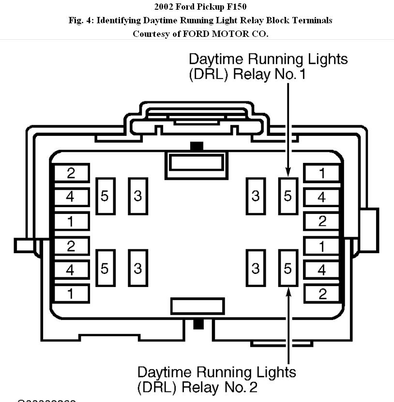
3. Remove DRL relay No. 2 from DRL relay block. If headlights go out, go to next step. If headlights remain illuminated, repair wiring as necessary between DRL relay No. 2 and central junction box.
4. Test DRL relay No. 2. See MICRO ISO RELAY under COMPONENT TESTS. If DRL relay No. 2 is okay, go to next step. If DRL relay No. 2 is defective, replace DRL relay No. 2.
5. Measure voltage between ground and DRL relay No. 2 harness connector terminal No. 2 (White/Black wire). See Fig. 4. If voltage does not exist, go to next step. If any voltage exists, repair short to voltage in White/Black wire between DRL relay No. 1 and DRL relay
No. 2.
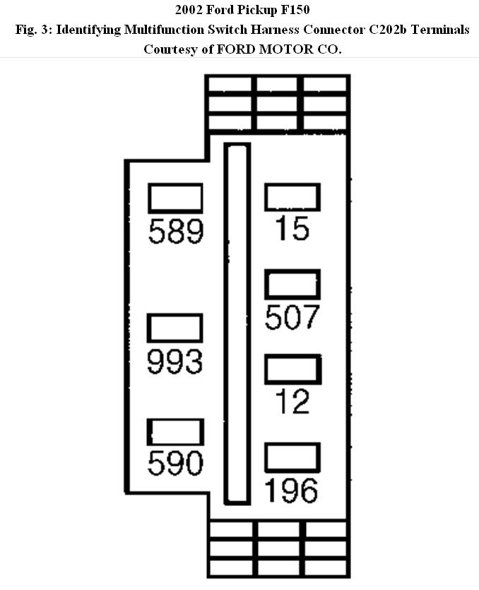
6. Disconnect multifunction switch 7-pin harness connector C202b. Measure voltage between ground and multifunction switch harness connector C202b terminal No. 2 (Red/Yellow wire). See Fig. 3. If voltage does not exist and vehicle is equipped with autolamps, go to next step. If voltage does not exist and vehicle is not equipped with autolamps, go to step 11. If any voltage exists, repair wiring as necessary between multifunction switch and central junction box.
7. Remove headlight relay. Headlight relay is located in RPO relay block No. 1. Test headlight relay. See MICRO ISO RELAY. If headlight relay is okay, go to next step. If headlight relay is defective, replace headlight relay.
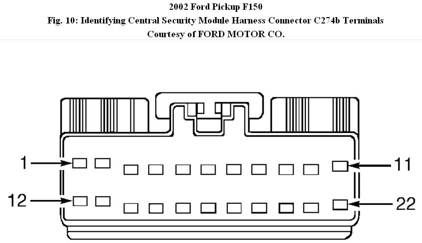
8. Disconnect autolamp module harness connector C287. Disconnect Central Security Module (CSM) module 22-pin harness connector C274b. Remove parking light relay from RPO relay block No. 1. See Fig. 10. Measure voltage between ground and headlight relay harness connector Light Green/Yellow wire. If battery voltage does not exist, go to next step. If any voltage exists, repair short to voltage in Light Green/Yellow wire between autolamp module and RPO relay block No. 1.
9. If headlights remain illuminated, go to next step. If headlights are not illuminated, check headlights while connecting CSM module and autolamp module. If headlights illuminate after connecting CSM module, replace CSM module. If headlights illuminate after connecting autolamp module, replace autolamp module.
10. Measure voltage between ground and multifunction switch harness connector C202b terminal No. 2 (Red/Yellow wire). See Fig. 3. If voltage does not exist, go to next step. If any voltage exists, repair wiring as necessary.
11. Test multifunction switch. If multifunction switch is defective, replace multifunction switch. If multifunction switch is okay, replace headlight switch.
12. Disconnect multifunction switch 7-pin harness connector C202b. Measure voltage between ground and multifunction switch harness connector C202b terminal No. 5 Gray/Orange wire. See Fig. 3. If any voltage exists, repair short to voltage in Gray/Orange wire. If voltage does not exist, replace multifunction switch.
MICRO ISO RELAY
1. Check relay continuity. Continuity should exist between relay terminals No. 1 and 2, and between relay terminals No. 3 and 4. See
Fig. 8. Continuity should not exist between relay terminals No. 3 and 5. If continuity is as specified, go to next step. If continuity is not as specified, replace relay.
2. Using a jumper wire, apply battery voltage to relay terminal No. 1. Using a second jumper wire, ground relay terminal No. 2. Continuity should now exist between relay terminals No. 3 and 5. If continuity is not as specified, replace relay. If continuity is as specified, relay is okay at this time.
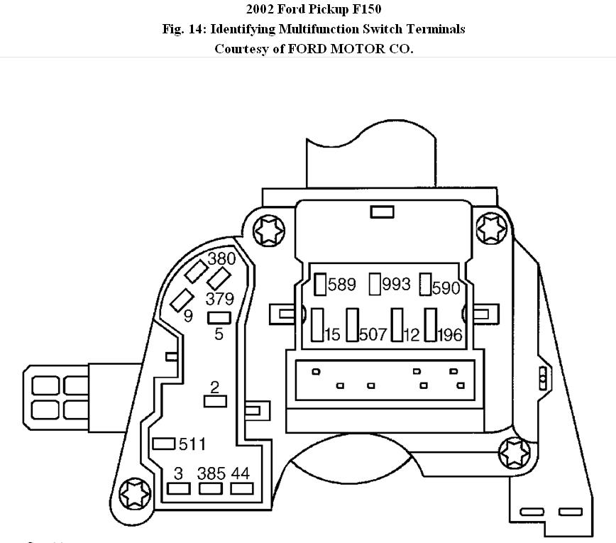
MULTIFUNCTION SWITCH
Remove multifunction switch.
Measure resistance between specified terminals while operating multifunction switch lever to specified positions.
See MULTIFUNCTION SWITCH TESTING table. See Fig. 14. If resistance is not as specified, replace multifunction switch.
Images (Click to make bigger)
SPONSORED LINKS
Wednesday, March 31st, 2021 AT 7:28 PM