If replacing the coil dose not help, you would have to chck the engine computer and the wiring circuit.
DTC P1305 : IGNITOR CIRCUIT MALFUNCTION
CAUTION:If ECM replacement is instructed in following testing, always ensure ECM harness connector and ground circuit are okay. If either are suspect, repair and repeat testing to confirm ECM malfunction. If
ECM is replaced, ECM must be programmed with proper ignition key code for engine immobilizer system.
Circuit Description
Vehicle is equipped with a Direct Ignition System (DIS), with a coil/ignitor devoted to each cylinder. Primary circuit is turned off when ECM delivers a signal to coil/ignitor on IGT wire, causing ignition coil/ignitor to fire spark plug. After delivering a command to turn off primary circuit on IGT wire, ECM monitors ignition confirmation signal on IGF circuit to ensure primary switching has occurred. If IGF signal is not input to ECM, ECM will stop fuel injection as a fail safe function. DTC will set if there is no IGF signal to ECM with engine running.
DTC 1305 is for cylinder No. 2.
Possible causes are:
†Open or short in IGF or IGT circuit.
†Faulty ignition coil/ignitor.
†Faulty ECM.
Diagnostic Aids
Using scan tool, read freeze frame data. Freeze frame records engine conditions when malfunction is detected.
Diagnosis & Repair
1. Check for spark at misfiring cylinder. If spark is present, go to next step. If spark is not present, go to step 4.
2. Check for open or short in IGF and IGT circuits between ECM E2 or E4 connector and suspect coil/ignitor. Repair as necessary. If circuits are okay, go to next step.
3. Disconnect suspect ignition coil/ignitor connector. Turn ignition on. Backprobing connector, measure voltage between ground and appropriate ECM connector E4 terminal as follows:
†For cylinders No. 1 or 7, measure voltage at terminal No. 6 (Light Green wire).
†For cylinders No. 2 or 8, measure voltage at terminal No. 5 (Blue/Black wire).
†For cylinders No. 3 or 5, measure voltage at terminal No. 4 (Green/Black wire).
†For cylinders No. 4 or 6, measure voltage at terminal No. 7 (Green wire).
See Fig. 3. If voltage is 4.5-5.5 volts, replace suspect ignition coil/ignitor. If voltage is not 4.5-5.5 volts, replace ECM and retest.
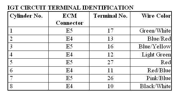
4. Check for open or short in IGT circuit between suspect ignition coil/ignitor and appropriate ECM connector terminal. See IGT CIRCUIT TERMINAL IDENTIFICATION table. Repair as necessary. If circuit is okay, go to next step.
5. If using an oscilloscope, go to next step. If not using an oscilloscope, access ECM at left front of engine compartment. Backprobing connector, measure voltage between ground and each IGT circuit terminal at appropriate ECM connector while cranking engine. If voltage is.1-4.5 volts, go to step 7. If voltage is not.1-4.5 volts, replace ECM and retest.
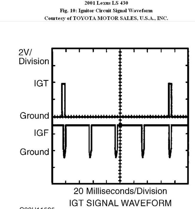
6. Backprobing connector, connect oscilloscope between terminal No. 7 (Brown wire) of ECM E6 connector and each IGT circuit terminal at appropriate ECM connector. Crank engine. Waveforms should be
as illustrated. See Fig. 10. If waveforms are as illustrated, go to next step. If waveforms are not as illustrated, replace ECM and retest.
7. Disconnect ignition coil connectors. Backprobing connector, measure voltage between ground and each IGT circuit terminal of appropriate ECM connector while cranking engine. If voltage is.1-4.5 volts, go
to next step. If voltage is not.1-4.5 volts, replace ECM and retest.
8. Disconnect suspect ignition coil/ignitor connector. Measure voltage between ground and suspect coil/ignitor harness connector terminal No. 1 (Red wire). Turn ignition switch to ON position, then to START position. If voltage is not 9-14 volts, repair ignition coil/ignitor
power source circuit. If voltage is 9-14 volts, go to next step.
9. Check for open in White/Black wire between suspect ignition coil/ignitor connector terminal No. 4 and ground. Repair as necessary. If circuit is okay, replace suspect ignition coil/ignitor.
Fig. 10: Ignitor Circuit Signal Waveform
Images (Click to make bigger)
SPONSORED LINKS
Sunday, February 20th, 2011 AT 2:16 PM


