Hi,
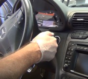
I have the diagnostics for this codes which I will provide. However, have you confirmed the inertia switch doesn't need reset? It's located in the left A pillar. See pic 1
Here are the diagnostics. The attached pics correlate with the directions. Note that the diagnostics are extensive.
_________________________________________
2001 Mercury Cougar V6-153 2.5L DOHC VIN L SFI
KB1 - KB47
Vehicle Powertrain Management Computers and Control Systems Testing and Inspection Pinpoint Tests KB: Fuel Pump Driver Module (FPDM) - Pinpoint Test KB1 - KB47
KB1 - KB47
KB: Fuel Pump Driver Module (FPDM)
KB: Introduction See: Computers and Control Systems > Pinpoint Tests > KB: Fuel Pump Driver Module (FPDM) - Introduction
KB1 DTC P1233 OR P1234: IS DTC P1233 OR P1234 PRESENT IN KEY ON ENGINE OFF SELF TEST
Is DTC P1233 or P1234 present in Key On Engine Off Self-Test?
Yes
- A hard fault is present. GO to KB2
.
No
- The PCM is now receiving a signal from the FPDM. One possible
cause of the DTC P1233 or P1234 is that the IFS switch was tripped, then reset.
- If engine is now a no start:
- Disregard the DTC P1233 or P1234 at this time. RETURN to Section 3 See: Computers and Control Systems > Symptom Related Diagnostic Procedures
and
CONTINUE as directed. After servicing the no start, to diagnose intermittent
causes of the DTC P1233 or P1234, RETURN to GO to KB25
.
- If engine will start:
- GO to KB25
to diagnose intermittent condition.
KB2 DOES THE ENGINE START?
Does the engine start?
Yes
- GO to KB15
(to check the FPM circuit).
No
- VERIFY IFS switch is set (button depressed). If OK, GO to KB3
.
KB3 CHECK POWER AND GROUND CIRCUITS TO FPDM
- Disconnect FPDM.
- Key on, engine off.
- Measure voltage between the FPDM PWR pin (VPWR for Continental) and ground pin at the FPDM harness connector.
Is voltage greater than 10.5 volts?
Pic 2
Yes
- Key off. REPLACE FPDM.
No
- GO to KB4
.
KB4 CHECK POWER TO FPDM
- Key on, engine off.
- Measure voltage between the FPDM PWR pin (VPWR for Continental) at the FPDM harness connector and chassis ground.
Is voltage greater than 10.5 volts?
Pic 3
Yes
- REPAIR open ground circuit to FPDM.
No
- KEY OFF. No power to FPDM.
- For Escort, Mustang:
- GO to KB5
.
- For Continental:
- GO to KB14
.
- All Others:
- GO to KB8
.
KB5 CHECK B+ VOLTAGE TO CCRM PIN 11 (FPDM POWER SUPPLY RELAY)
- Disconnect CCRM.
- Measure B+ circuit voltage at Pin 11 of the CCRM harness connector.
Is voltage greater than 10.5 volts?
Yes
- For Mustang:
- GO to KB6
.
- For Escort:
- GO to KB7
.
No
- VERIFY integrity of related fuse. If OK, REPAIR open B+ circuit.
If fuse is damaged, CHECK B+ and FPDM PWR circuits for short to ground before
replacing.
KB6 CHECK GROUND CIRCUIT TO CCRM PIN 18
- Measure resistance of ground circuit between CCRM harness connector Pin 18 and chassis ground.
Is resistance less than 5.0 ohms?
Yes
- GO to KB7
.
No
- SERVICE open ground circuit.
KB7 CHECK FOR OPEN FPDM PWR CIRCUIT
- Measure resistance of FPDM PWR circuit between CCRM harness connector (pin 5) and FPDM harness connector.
Is resistance less than 5.0 ohms?
Yes
- REPLACE CCRM.
No
- The FPDM PWR circuit is open. GO to KB13
to help
isolate fault.
KB8 CHECK B+ VOLTAGE TO FPDM POWER SUPPLY RELAY
- Disconnect FPDM power supply relay.
- Measure B+ circuit voltage at the FPDM power supply relay harness connector.
Is voltage greater than 10.5 volts?
Yes
- GO to KB9
.
No
- VERIFY integrity of related fuse. If OK, REPAIR open B+ circuit.
If fuse is damaged, CHECK B+ and FPDM PWR circuits for short to ground before
replacing.
KB9 CHECK FOR GROUND TO FPDM POWER SUPPLY RELAY
- Disconnect scan tool from DLC.
- Measure resistance of ground circuit between FPDM power supply relay harness connector and battery negative post.
Is resistance less than 5.0 ohms?
Yes
- GO to KB10
.
No
- REPAIR open circuit.
KB10 CHECK FOR OPEN FPDM PWR CIRCUIT
- Measure resistance of FPDM PWR circuit between FPDM power supply relay harness connector and FPDM harness connector.
Is resistance less than 5.0 ohms?
Yes
- RECONNECT FPDM. GO to KB11
.
No
- The FPDM PWR circuit is open. GO to KB13
to help
isolate fault.
KB11 CHECK VPWR CIRCUIT VOLTAGE TO FPDM POWER SUPPLY RELAY
- Key on, engine off.
- Measure VPWR circuit voltage at the FPDM power supply relay harness connector.
Is voltage greater than 10.5 volts?
Yes
- REPLACE FPDM power supply relay.
No
- REPAIR open VPWR circuit.
KB13 ISOLATE OPEN IN FPDM PWR CIRCUIT
- Disconnect IFS switch.
- Measure resistance of FPDM PWR circuit between IFS switch harness connector and FPDM power supply relay harness connector (for Escort, CCRM harness connector [pin 5]).
- Measure resistance of FPDM PWR circuit between FPDM harness connector and IFS switch harness connector.
Are both resistances less than 5.0 ohms?
Yes
- VERIFY that the IFS switch is set (button depressed). If OK,
REPLACE IFS switch.
No
- REPAIR open in appropriate area of FPDM PWR circuit.
KB14 ISOLATE OPEN IN VPWR CIRCUIT TO FPDM
- Disconnect Electronic Engine Control (EC) Power Relay.
- Disconnect IFS switch.
- Measure resistance of VPWR circuit between IFS switch harness connector and electronic EC power relay harness connector.
- Measure resistance of VPWR circuit between IFS switch harness connector and FPDM harness connector.
Are both resistances less than 5.0 ohms?
Yes
- VERIFY that the IFS switch is set (button depressed). If OK,
REPLACE IFS switch.
No
- REPAIR open in the appropriate area of the VPWR circuit to the
FPDM.
KB15 CHECK FOR OPEN FPM CIRCUIT
- Disconnect FPDM.
- Disconnect PCM.
- Measure resistance of FPM circuit between PCM harness connector Pin 40 and the FPDM harness connector.
Is resistance less than 5.0 ohms?
Yes
- GO to KB16
.
No
- REPAIR open circuit.
KB16 CHECK FPM CIRCUIT FOR SHORT TO POWER IN HARNESS
- Key on, engine off.
- Measure voltage between PCM harness connector Pin 40 and ground.
Is voltage less than 1.0 volt?
Yes
- KEY OFF. GO to KB17
.
No
- REPAIR short circuit.
KB17 CHECK FPM CIRCUIT FOR SHORT TO GROUND IN HARNESS
- Disconnect scan tool from DLC.
- Measure resistance between PCM harness connector Pin 40 and ground.
Is resistance greater than 10,000 ohms?
Yes
- GO to KB18
.
No
- REPAIR short circuit.
KB18 CHECK FOR FPM OUTPUT FROM FPDM
- Reconnect FPDM.
- Key on, engine off.
- Measure dc voltage between PCM harness connector Pins 40 and 51.
Is voltage between 0.02 and 1.0 volt dc? (It is OK for the voltage to cycle below this range and then return to within range.)
Yes
- REPLACE PCM (refer to Section 2, Flash Electrically Erasable Programmable Read Only Memory (EEPROM) See: Computers and Control Systems > Programming and Relearning > Flash Electrically Eraseable Programmable Read Only Memory - Flash EEPROM).
No
- REPLACE FPDM.
KB25 CHECK CIRCUITS THAT MAY CAUSE AN INTERMITTENT LOSS OF POWER SUPPLY TO THE FPDM. ALSO CHECK FOR INTERMITTENT OPENS OR SHORTS ON THE FPM CIRCUIT.
- Key on, engine off.
- Access FP M PID on scan tool.
Note:With no fault detected, the FPDM will send a 50% duty cycle signal (all OK) to the PCM on the FPM circuit. Depending on scan tools, the FP_M PID may display 50%, or a random value that is fluctuating between 85 and 115%.
- Observe FP M PID for an indication of a fault while completing the following (look for the FP M PID to change from the 50% value, or to stop fluctuating):
- Shake, wiggle, bend the following circuits:
- FPDM ground.
- Power supply circuit (VPWR or FPDM PWR) to FPDM.
- For Escort and Mustang, the B+ circuit to CCRM pin 11. For Mustang, also the ground circuit to CCRM Pin 18.
- For Focus, Contour/Mystique/Cougar, Taurus/Sable, the B+ and ground circuits to FPDM power supply relay.
- FPM circuit between the FPDM and the PCM.
- Lightly tap on the IFS Switch, FPDM and CCRM or FPDM power supply relay to simulate road shock.
- Key off.
Is a fault indicated?
Yes
- ISOLATE fault and REPAIR as necessary.
No
- Unable to duplicate or identify fault at this time. GO to Z1 See: Computers and Control Systems > Diagnostic Trouble Code Tests and Associated Procedures > Z: Intermittent - Pinpoint Test
.
KB30 DTC P1235 OR P1236: IS DTC P1235 OR P1236 PRESENT IN KEY ON ENGINE OFF OR ENGINE RUNNING SELF TEST?
Note:Refer to the PCM connector pin numbers in the beginning of this pinpoint test.
Note:For LS6/LS8, the FPDM functions are incorporated in the Rear Electronics Module (REM). In the following steps, if directed to perform an action with the FPDM, complete the action with the REM. Refer to the pin numbers in the beginning of this pinpoint test.
Is DTC P1235 or P1236 present in Key On Engine Off or Engine Running Self-Test?
Yes
- A hard fault is present. GO to KB31
to check the
FP circuit.
No
- DTC P1235 or P1236 is intermittent.
- For LS6/LS8
:
- GO to KB42
.
- All others
:
- GO to KB45
.
KB31 CHECK FOR OPEN FP CIRCUIT BETWEEN PCM AND FPDM
- Disconnect FPDM.
- Disconnect PCM.
- Measure resistance of FP circuit between PCM harness connector pin and the FPDM harness connector.
Is resistance less than 5.0 ohms?
Yes
- GO to KB32
.
No
- REPAIR open circuit.
KB32 CHECK FP CIRCUIT FOR SHORT TO POWER IN HARNESS
- Key on, engine off.
- Measure voltage between FP circuit at PCM harness connector pin and ground.
Is voltage less than 1.0 volt?
Yes
- KEY OFF. GO to KB33
.
No
- REPAIR short circuit.
KB33 CHECK FP CIRCUIT FOR SHORT TO GROUND IN HARNESS
- Disconnect scan tool from DLC.
- Measure resistance between FP circuit at PCM harness connector pin and ground.
Is resistance greater than 10,000 ohms?
Yes
- For LS6/LS8
:
- GO to KB36
.
- All others
:
- GO to KB34
.
No
- REPAIR short circuit.
KB34 CHECK FP CIRCUIT IN FPDM
- Reconnect FPDM.
- Key on, engine off.
- Measure voltage between FP circuit at PCM harness connector pin and ground.
Is voltage between 4.5 and 5.5 volts?
Yes
- REPLACE PCM (refer to Section 2, Flash Electrically Erasable Programmable Read Only Memory (EEPROM) See: Computers and Control Systems > Programming and Relearning > Flash Electrically Eraseable Programmable Read Only Memory - Flash EEPROM).
No
- REPLACE FPDM.
KB36 CHECK FPF PID
- Key on, engine off.
- Access the FP and FPF PIDs on the scan tool (the FP PID may be used in the next step).
- While viewing the FPF PID for 20 seconds, check if the FPF PID will indicate YES. The FPF PID may read NO in the 20 seconds, but will change back to YES.
Does the FPF PID indicate YES within 20 seconds?
Yes
- GO to KB40
.
No
- GO to KB37
.
KB37 CHECK FP PID
Does the FP PID indicate between 70 and 80%?
Yes
- GO to KB38
.
No
- TURN KEY OFF then back ON. Wait 5 seconds. REPEAT test step.
If result is now YES, follow YES result. If result is still NO, REPLACE PCM
(refer to Section 2, Flash Electrically Erasable Programmable Read Only Memory (EEPROM) See: Computers and Control Systems > Programming and Relearning > Flash Electrically Eraseable Programmable Read Only Memory - Flash EEPROM).
KB38 ACCESS REM PIDS AND CHECK PWM_DC1 PID
- Access the PWM_DC1 PID from the REM menu (the PWM_DC1 PID indicates the signal sent to the REM from the PCM on the FP circuit).
Does the PWM_DC1 PID indicate between 70 and 80%?
Yes
- KEY OFF. No fault indicated. Disregard DTC P1235 or P1236. RETURN
to Section 3 See: Computers and Control Systems > Symptom Related Diagnostic Procedures
where DTC was received and proceed as directed.
No
- REPLACE REM.
KB40 CHECK REM CIRCUITRY VOLTAGE ON FP CIRCUIT AT PCM
- Key off.
- Disconnect PCM connector A.
- Key on, engine off.
- Measure voltage between Pin A58 at the PCM harness connector A and ground.
Is voltage greater than 8 volts?
Yes
- REPLACE PCM (refer to Section 2, Flash Electrically Erasable Programmable Read Only Memory (EEPROM) See: Computers and Control Systems > Programming and Relearning > Flash Electrically Eraseable Programmable Read Only Memory - Flash EEPROM).
No
- REPLACE REM.
KB42 CHECK FP CIRCUIT FOR INTERMITTENT CONCERNS
- Key on, engine off.
- Access the REM PID access menu on the scan tool.
- Access the PWM_DC1 PID from the REM menu (the PWM_DC1 PID indicates the signal sent to the REM from the PCM on the FP circuit).
- Observe the PWM_DC1 PID for indication of a fault while completing the following (the PID value will change when a fault is detected):
- Shake, wiggle and bend the FP circuit between the PCM (Pin A58) and REM (Pin J2-19).
Is a fault indicated?
Yes
- ISOLATE fault and REPAIR as necessary.
No
- KEY OFF. Unable to duplicate or identify fault at this time. GO to Z1 See: Computers and Control Systems > Diagnostic Trouble Code Tests and Associated Procedures > Z: Intermittent - Pinpoint Test
with the following data: PWM_DC1 PID (REM menu), FP PID
(PCM menu, the FP PID is the signal the PCM is sending to the REM).
KB45 CHECK FP CIRCUIT FOR INTERMITTENT OPENS OR SHORTS
- Key on, engine off.
- Access FP M PID on scan tool.
Note:With no fault detected, the FPDM will send a 50% duty cycle signal (all OK) to the PCM on the FPM circuit. Depending on scan tools, the FP M PID may display 50%, or a random value that is fluctuating between 85 and 115%.
- Observe the FP M PID for an indication of a fault while completing the following (look for the FP M PID to change from the 50% value, or to stop fluctuating):
- Shake, wiggle, bend the FP circuit between FPDM and the PCM.
- Lightly tap on the FPDM (to simulate road shock).
Is a fault indicated?
Yes
- ISOLATE fault and REPAIR as necessary.
No
- KEY OFF. Unable to duplicate or identify fault at this time. GO to Z1 See: Computers and Control Systems > Diagnostic Trouble Code Tests and Associated Procedures > Z: Intermittent - Pinpoint Test
.
KB47 DTC P1237 OR P1238: IS DTC P1237 OR P1238 PRESENT IN KEY ON ENGINE OFF OR ENGINE RUNNING SELF TEST
Is DTC P1237 or P1238 present in Key On Engine Off or Key On Engine Running Self-Test?
Yes
- A hard fault is present. GO to KB48
.
No
- DTC P1237 or P1238 is possibly intermittent.
- For LS6/LS8
:
- GO to KB67
.
- All others
:
- GO to KB56.
Continued: See: Computers and Control Systems > Pinpoint Tests > KB48 - KB86
_____________________________________
Let me know if this helps or if you have other questions.
Joe
Images (Click to make bigger)
SPONSORED LINKS
Thursday, October 22nd, 2020 AT 4:55 PM