Glad to know you like it here and thanks for the compliment.
Since we have a trouble code which could be related to the problem, I would advise going through the diagnostic procedures to see if we can come up with anything.
P0725 = Engine Speed Input Circuit.
Diagnostic procedures.
CAN-Bus terminal resistance, Transmission Control Module (TCM) J217 to Engine Control Module (ECM) J220 , checking.
The Motronic Engine Control Module (ECM) J220 communicates with all databus capable control modules via a CAN databus.
These databus capable control modules are connected via two data bus wires which are twisted together (CAN_High and CAN_Low), and exchange information (messages). Missing information on the databus is recognized as a malfunction and stored.
Trouble-free operation of the CAN-bus requires that it have a terminal resistance. The central terminal resistor is located in the Engine Control Module (ECM) J220.
Special tools, testers and auxiliary items required
"¢ Multimeter.
"¢ Wiring diagram.
Test requirement
"¢ A CAN-Bus malfunction was recognized.
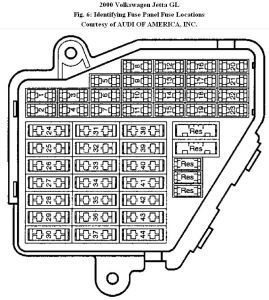
"¢ The Engine Control Module (ECM) J220 fuses OK.
"¢ Battery voltage at least 12.5 V.
"¢ Ignition switched off.
Test procedure
◦ Perform a preliminary check to verify the customers complaint. Refer to → Motronic Engine Control Module (ECM) J220 , replacing
Start diagnosis
Removal
â—¦ Remove the center dash panel - 1 - in the direction of the - arrow -.
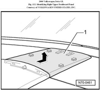
â—¦ Remove the right upper dashboard panel.
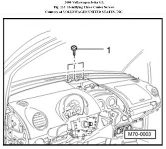
â—¦ Remove the three center screws - 1 -
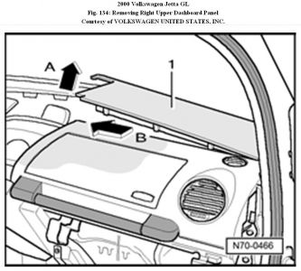
â—¦ Remove the right upper dashboard panel - 1 - in the direction of - arrow A - and - arrow B -.
â—¦ Pull the Transmission Control Module (TCM) J217 electrical harness electrical connector - 1 - retaining tab in the direction of the - arrow - and remove from the Transmission Control Module (TCM) J217 - 2 -.
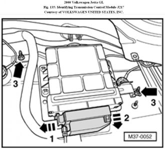
â—¦ Remove the retaining nuts - 3 - and the Transmission Control Module (TCM) J217 - 2 - in the direction of the -
arrow -.
NOTE:
"¢ The Engine Control Module (ECM) J220 must remain connected for the following step.
â—¦ Using a Multimeter , check the Transmission Control Module (TCM) J217 electrical harness connector T68 terminals 3 to 25 for resistance.
Specified value: 60 to 72 Ω (at approx. 20 ° C)
If the specified value was not obtained:
â—¦ Check the wiring connection for an open circuit, short circuit to Battery (+) or Ground (GND).
â—¦ Check the wiring connection for damage, corrosion, loose or broken terminals.
â—¦ If necessary, repair the faulty wiring connection.
If no malfunction is found in the wiring:
Replace the Transmission Control Module (TCM) J217. Refer to → Motronic Engine Control Module (ECM) J220 , replacing .
If the specified value was obtained:
â—¦ Checking wiring
If the manufacturers test box is being used. Perform the following step.
â—¦ Install the Adapter F/VAG1598 (68 Pin) VAG1598/22
â—¦ Install the Adapter - 68 Pin VAG1598/18. Refer to
38 AUTOMATIC TRANSMISSION - GEARS, HYDRAULIC CONTROLS for 4 SPD. AUTOMATIC TRANSMISSION 01M and 38 - AUTOMATIC TRANSMISSION - GEARS, HYDRAULIC CONTROLS for 5 SPD. AUTOMATIC TRANSMISSION 09A .
If the manufacturers test box is not being used. Perform the following step.
◦ Remove the Engine Control Module (ECM) J220. Refer to → Motronic Engine Control Module (ECM) J220 , replacing.
â—¦ Using a Multimeter , check the Transmission Control Module (TCM) J217 electrical harness connector T68 to the Engine Control Module (ECM) J220 electrical harness
connector T80 for resistance.
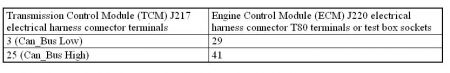
Specified value: 1.5 Ω Max.
If the specified value was not obtained:
â—¦ Check the wiring connection for an open circuit, short circuit to Battery (+) or Ground (GND).
â—¦ Check the wiring connection for damage, corrosion, loose or broken terminals.
â—¦ If necessary, repair the faulty wiring connection.
If no malfunction is found in the wiring:
◦ Erase the DTC memory. Refer to → Diagnostic Mode 04: Reset/delete diagnostic data
â—¦ Perform a road test to verify repair.
If the DTC does not return:
Repair complete, Generate readiness code. Refer to →
Readiness Code .
â—¦ End diagnosis.
If the DTC does return and no malfunction is detected in the wiring and the voltage supply was OK:
◦ Replace the Motronic Engine Control Module (ECM) J220. Refer to → Motronic Engine Control Module (ECM) J220 , replacing .
â—¦ Assembly is performed in the reverse of the removal.
Final procedures
After the repair work, the following work steps must be performed in the following sequence:
1. Check the DTC memory. Refer to.
2. If necessary, erase the DTC memory.
3. If the DTC memory was erased, generate readiness code.
End of diagnosis
Additional diagnostic prodcedures wil be sent to your email as they are rather lengthy.
Oct 1, 2010 at 7:53 AM