Here are the diagnostic procedures.
TEST Q: MODE DOOR FEEDBACK FAILURE MODE DOOR STALL TEST FAILURE
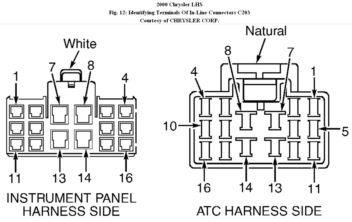
1. Turn ignition switch to OFF position. Locate in-line harness connector C203 (behind center of instrument panel, above accelerator pedal). See Fig. 12. Turn ignition switch to ON position. Using DVOM connected to ground, backprobe 5-volt supply circuit at in-line connector C203 terminal No. 6 (Pink/Dark Blue wire). If reading is zero volts, go to next step. If reading is 4.5-5.5 volts, go to step
7. If reading is 5.5 volts or more, go to step 19.
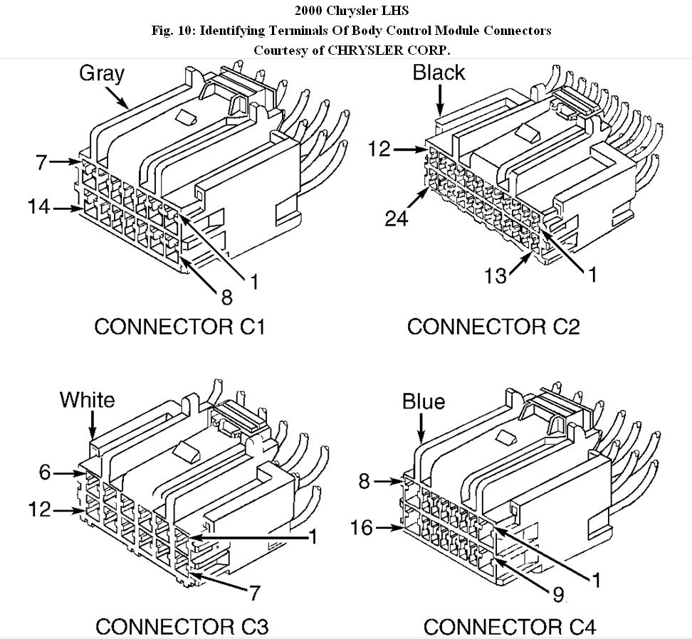
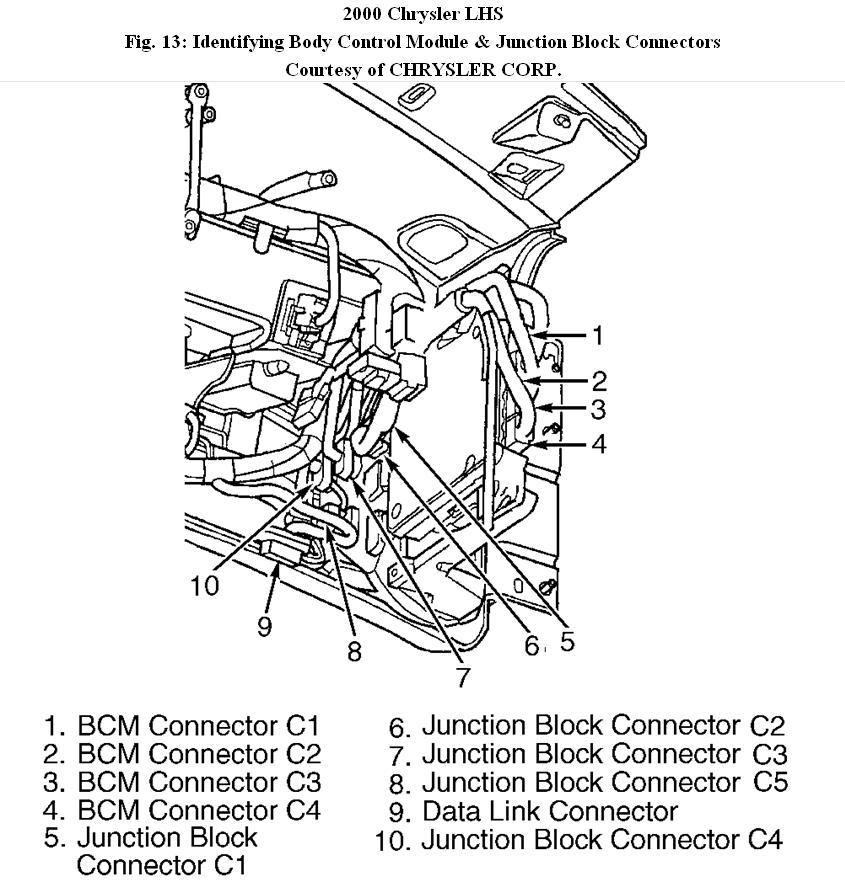
2. Turn ignition switch to OFF position. Disconnect in-line connector C203. Disconnect Body Control Module (BCM) connector C2. See Fig. 13. Measure resistance between ground and 5-volt supply circuit at BCM connector C2 terminal No. 15 (Pink/Dark Blue wire). See Fig. 10. If reading is 100 ohms or more, go to next step. If reading is less than 100 ohms, repair short to ground in Pink/Dark Blue wire. After any repair, go to step 20.
3. Measure resistance of Pink/Dark Blue wire between BCM connector C2 terminal No. 15 and in-line connector C203 terminal No. 6 (instrument panel harness side). See Fig. 10 and Fig. 12 . If reading is less than 5 ohms, go to next step. If reading is 5 ohms or more, repair open in Pink/Dark Blue wire. After any repair, go to step 20.
4. Turn ignition switch to OFF position. Connect in-line connector C203. See Fig. 12. Disconnect BCM connectors C1 and C2. See Fig. 10. Measure resistance between BCM connector C1 terminal No. 8 (Dark Blue/Gray wire) and BCM connector C2 terminal No. 15 (Pink/Dark Blue wire). If reading is less than 2000 ohms, go to next step. If reading is 2000 ohms or more, replace BCM. After repair, go to step 20.
5. Turn ignition switch to OFF position. Disconnect blend door actuator connector. Measure resistance between BCM connector C1 terminal No. 8 (Dark Blue/Gray wire) and BCM connector C2 terminal No. 15 (Pink/Dark Blue wire). See Fig. 10. If reading is less than 2000 ohms, go to next step. If reading is 2000 ohms or more, replace blend door actuator. After repair, go to step 20.
6. Turn ignition switch to OFF position. Disconnect mode door actuator connector. Measure resistance between BCM connector C1 terminal No. 8 (Dark Blue/Gray wire) and BCM connector C2 terminal No. 15 (Pink/Dark Blue wire). See Fig. 10. If reading is less than 2000 ohms, repair short between Pink/Dark Blue wire and Dark Blue/Gray wire. If readings is 2000 ohms or more, replace mode door actuator. After repair, go to step 20.
7. Connect in-line connector C203. See Fig. 12. Turn ignition switch to ON position. Using scan tool, read MODE DOOR value. If reading is less than .3 volts, go to step 15. If reading is .3-5.5 volts, go to next step. If reading is 5.6 volts or more, repair short to voltage in mode door feedback signal circuit at BCM connector C2 terminal No. 9 (Yellow/White wire. After repair, go to step 20.
8. Turn ignition switch to OFF position. Disconnect in-line connector C203. See Fig. 12. Ensure all lighting is turned off. Close all doors (dome light off). Measure resistance between ground and instrument panel harness side of in-line connector C203 terminal No. 5 (Dark Blue/Gray wire). See Fig. 12. If reading is less than 5 ohms, go to next step. If reading is 5 ohms or more, go to step 14.
9. Disconnect BCM connector C1. Measure resistance of Brown/White wire between BCM connector C1 terminal No. 10 and in-line connector C203 terminal No. 1 (ATC harness side). See Fig. 10 and Fig. 12 . If reading is less than 5 ohms, go to next step. If reading is 5 ohms or more, repair open in common door driver circuit (Brown/White wire). After repair, go to step 20.
10. Measure resistance of Dark Green/Yellow wire between in-line connector C203 terminal No. 2 and BCM connector C1 terminal No. 9. See
Fig. 10 and Fig. 12 . If reading is less 10. than 5 ohms, go to next step. If reading is 5 ohms or more, repair open in mode door driver circuit (Dark Green/Yellow wire). After repair, go to step 20.
11. Turn ignition switch to OFF position. Connect all previously disconnect connectors. Clear DTCs stored in memory. Disconnect BCM connector C1. Connect DVOM between chassis ground and BCM connector C1 terminal No. 10 (Brown/White wire). See Fig. 10. Reconnect BCM connector C1. Turn ignition switch to ON position. While observing DVOM display, turn off recirculation switch, turn on panel mode, then turn on recirculation switch. If reading goes above 10 volts, go to next step. If reading remains less than 10 volts, replace BCM. After repair, go to step 20.
12. Turn ignition switch to OFF position. Clear DTCs stored in memory. Using DVOM connected to chassis ground, backprobe BCM connector C1 terminal No. 9 (Dark Green/Yellow wire). See Fig. 10. Reconnect BCM connector C1. Turn ignition switch to ON position. While monitoring DVOM display, change ATC control panel modes between defrost to panel settings several times. If reading goes above 10 volts, go to next step. If reading remained less than 10 volts, replace BCM. After repair, go to step 20.
13. Inspect wiring and connectors for mode door actuator. Repair wiring or connectors as necessary. Check mode door operation for a binding condition. Repair binding condition as necessary. If wiring and mode door operation is okay, replace mode door actuator. After
repair, go to step 20.
14. Turn ignition switch to OFF position. Disconnect in-line connector C203. Disconnect BCM connector C1. Measure resistance of Dark Blue/Gray wire between in-line connector C203 terminal No. 5 (instrument panel harness side) and BCM connector C1 terminal No. 8. See Fig. 10 and Fig. 12 . If reading is less than 5 ohms, replace BCM. If reading is 5 ohms or more, repair open in sensor ground circuit (Dark Blue/Gray wire). After repair, go to step 20.
15. Turn ignition switch to OFF position. Disconnect in-line connector C203. Disconnect BCM connector C2. Measure resistance between ground and BCM connector C2 terminal No. 9 (Yellow/White wire). See Fig. 10. If reading is 1000 ohms or more, go to next step. If reading is less than 1000 ohms, repair short to ground in Yellow/White wire. After repair, go to step 20.
16. Disconnect in-line connector C203. Disconnect BCM connector C2. Measure resistance of Yellow/White wire between BCM connector C2 terminal No. 9 and in-line connector C203 terminal No. 11. See Fig. 10 and Fig. 12. If reading is less than 5 ohms, go to next step. If reading is 5 ohms or more, repair open in Yellow/White wire. After repair, go to step 20.
17. Disconnect BCM connector C1. Measure resistance between BCM connector C1 terminal No. 8 (Dark Blue/Gray wire) and BCM connector C2 terminal No. 9 (Yellow/White wire). See Fig. 10. If reading is 1000 ohms or more, go to next step. If reading is less than 1000 ohms, repair short between Dark Blue/Gray wire and Yellow/White wire. After repair, go to step 20.
18. Ensure ignition switch is in OFF position. Connect BCM connectors C1 and C2. See Fig. 10. Turn ignition switch to ON position. Using scan tool, display MODE DOOR value. While observing scan tool, connect a jumper wire between in-line connector C203 (instrument panel harness side) terminals No. 6 (Pink/Dark Blue wire) and No. 11 (Yellow/White wire). See Fig. 12. If scan tool displays value of about 5 volts, replace mode door actuator. If scan tool does not display value of about 5 volts, replace BCM. After repair, go to step 20.
19. Turn ignition switch to OFF position. Disconnect BCM connector C2. Turn ignition switch to ON position. Using DVOM connected to ground, backprobe 5-volt supply circuit at BCM connector C2 terminal No. 15 (Pink/Dark Blue wire). See Fig. 10. If reading indicates voltage present, repair short to voltage in Pink/Dark Blue wire. If reading indicates no voltage is present, replace BCM. After either repair, calibrate mode door. After repair, go to next step.
20. Perform calibration of A/C-heater housing actuator doors. Perform verification test.
© 2008 Mitchell Repair Information Co., LLC.
Images (Click to enlarge)
Jan 21, 2011 at 2:23 AM