Hi,
Is the 4wd light turning on indicating the transfer case is engaged? If not, check to make sure the shift linkage to it is properly attached and sifting.
If that isn't a consideration, then chances are one of the hub assemblies has gone bad and allowing the axle to turn without engagement. I don't know if you have automatic locking hubs or manual, so I will provide directions for removal and replacement of both. I'll start with the manual locking. When taking it apart, check for excessive play or any damage to the components that can cause the problem. The attached pics correlate with the directions.
_________________________________________
1991 Isuzu Truck Trooper II V6-2827cc 2.8L
Manual Locking Hub
Vehicle Steering and Suspension Wheels and Tires Wheel Hub (Locking) Service and Repair Procedures Disassembly and Assembly Manual Locking Hub
MANUAL LOCKING HUB
DISASSEMBLY
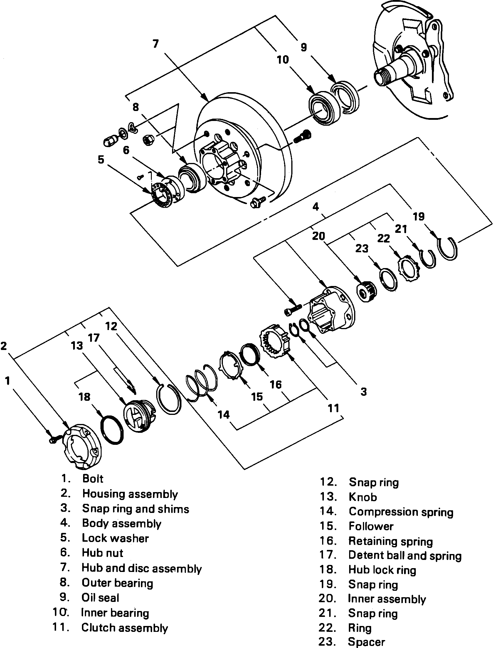
1. Remove outer bearing, oil seal and inner bearing.
2. While pushing follower knob, turn clutch assembly clockwise and remove clutch assembly from knob.
3. Remove snap ring, knob, compression spring and follower.
4. Turn clutch assembly retaining spring clockwise and remove from assembly.
5. Remove detent ball and spring.
6. Remove hub lock ring, snap ring, inner assembly, snap ring, ring and spacer.
Fig. 21 Exploded view of manual locking hub.
Pic 1
ASSEMBLY
1. Apply grease to both faces of spacer and install.
2. Apply grease to inside face of ring and install.
3. Install snap ring, then apply grease to splined portion of inner assembly body and install.
4. Install snap ring, hub lock ring, detent ball and spring, Fig. 21.
5. Apply grease to outer circumference of knob and inner circumference of cover.
6. Align detent ball with groove of cover and install knob.
7. Install snap ring with smooth surface toward knob.
8. Install clutch assembly retaining spring.
9. Install follower to clutch. Ensure follower nail comes close to the bent portion of retaining spring by aligning follower stopper nail to outer teeth of clutch, then hook retaining spring onto upper portion of hanger nails of follower.
10. Install compression spring with smaller diameter toward follower.
11. Install clutch assembly as follows:
a. Align follower nail to handle groove then assemble clutch with knob by pushing and turning clutch counterclockwise to knob.
12. Using tools J-36828 and J-8092 or equivalent, install two outer races then two outer bearings.
13. Coat hub with grease, then apply Besco L-2 or equivalent to inner and outer bearing.
14. Turn hub so chamfer is aligned to the tapped hole on outer side, then using tool J-36827 or equivalent, install hub nut.
15. Using a spring scale, adjust bearing preload to 3.03 lbs.
16. Install lock washer with larger diameter of the tapered bore to the outer side of vehicle. If bolt holes in the lock plate are not aligned with the corresponding holes in the nut, reverse the lock plate. If bolt holes are still out of alignment, turn nut enough to obtain alignment. Ensure screw is fastened tightly so head is lower than surface of washer.
17. Apply Loctite 515 or equivalent, to body assembly and install.
18. Install snap ring and shims, then adjust clearance between free wheeling hub body and snap ring. Clearance should be 0.01 inch. Available adjusting shim are .008, .011, .020 and .039.
19. Align and install cover assembly torquing bolts to 8.7 ft. lbs.
__________________________________________________________________________________________
1991 Isuzu Truck Trooper II V6-2827cc 2.8L
Automatic Locking Hub
Vehicle Steering and Suspension Wheels and Tires Wheel Hub (Locking) Service and Repair Procedures Disassembly and Assembly Automatic Locking Hub
AUTOMATIC LOCKING HUB
DISASSEMBLY
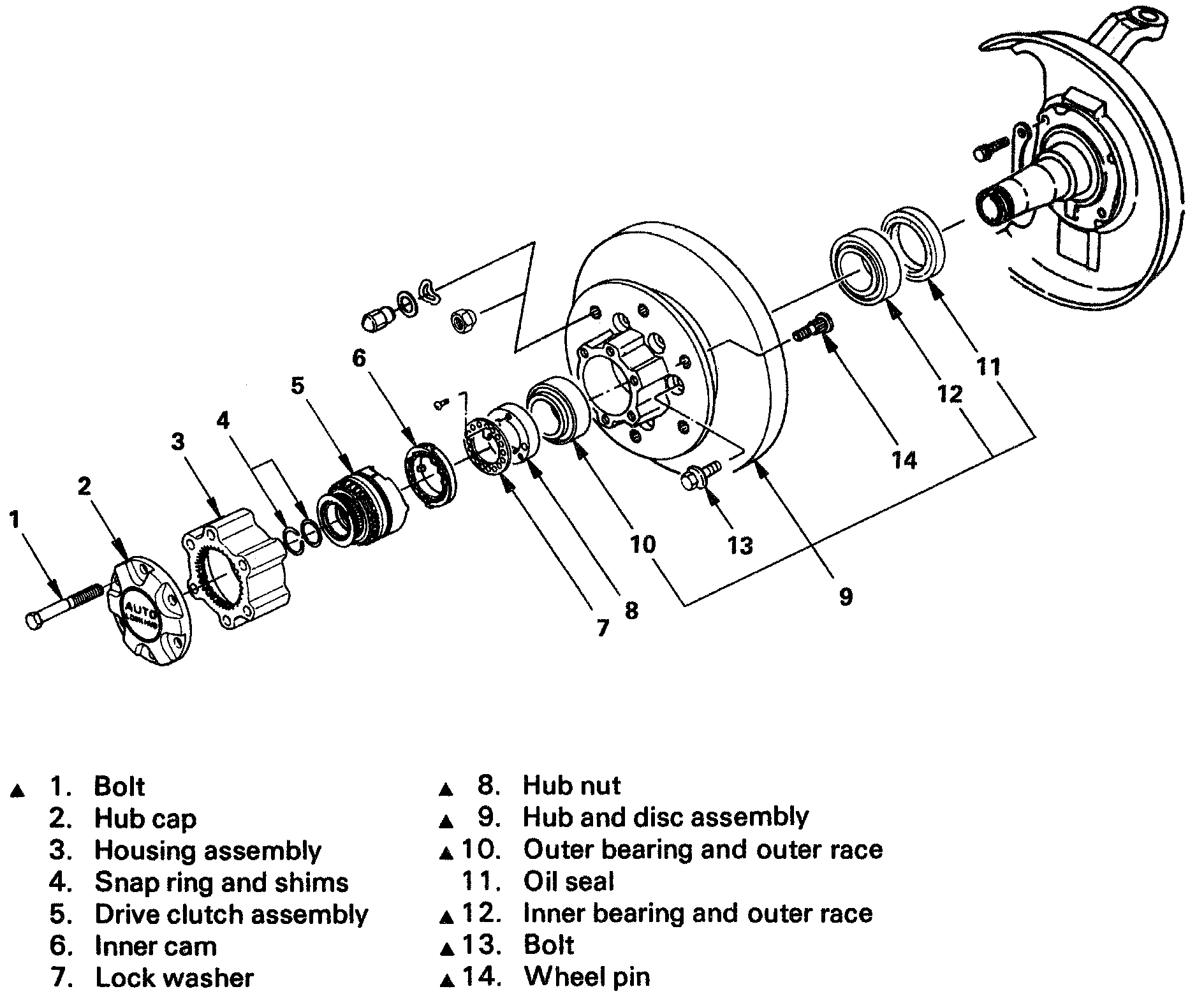
1. Remove outer bearing and outer race from hub.
2. Remove oil seal, then using a drift, remove outer bearing race then the inner bearing.
3. Apply a scribe mark to both rotor and hub, then remove six rotor to hub retaining bolts.
4. Using a hammer, remove wheel studs as required.
ASSEMBLY
1. Install wheel studs if removed.
2. Align scribe marks on hub and rotor then install six retaining bolts and torque to 76 ft. lbs.
3. Using tools J-36828 and J-8092 or equivalent, install outer race.
4. Repeat step 3 for installation of outer bearing and outer race.
5. Install inner bearing, then using tools J-36828 and J-8092 or equivalent, install oil seal.
6. Coat inner hub with grease, then apply Besco L-2 or equivalent to inner and outer bearing.
7. Turn hub so chamfer is aligned to the tapped hole on outer side, then using tool J-36827 or equivalent, install hub nut.
8. Using a spring scale, adjust bearing preload to 3.31 lbs.
9. Install lock washer with larger diameter of the tapered bore to the vehicle. If bolt holes in the lock plate are not aligned with the corresponding holes in the nut, reverse the lock plate. If bolt holes are still out of alignment, turn nut enough to obtain alignment. Ensure screw is fastened tightly so head is lower than surface of washer.
10. With transfer lever still in the ``2H'' position, install inner cam with cam gear facing out.
11. Lower vehicle from hoist, then support lower link with floor jack placing axle in normal position.
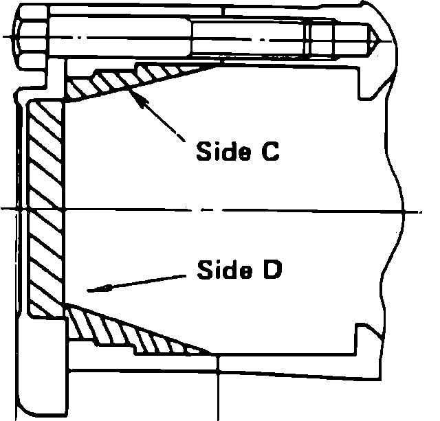
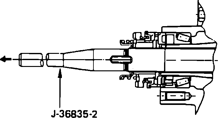
Fig. 17 Exploded View Of Automatic Locking Hub
pic 2
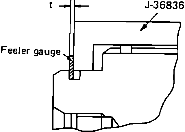
Fig. 18 Measuring axle shaft snap ring clearance
pic 3
12. Install tool J-36836 to axle shaft by tool J-36835-2 or equivalent, Fig. 17, then measure clearance ``t'' Fig. 18, between tool and snap ring groove of axle shaft using a feeler gauge.
13. Clearance should be .0039. If clearance is larger than specified, select proper shim to meet specification.
14. Remove tool J-36836 and ensure inner cam stays in place. If inner cam is removed, repeat steps 10-13.
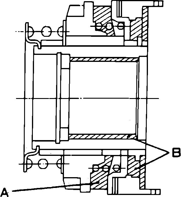
Fig. 19 Application of drive clutch assembly lubricant (Part 1 of 2)
pic 4
Fig. 19 Application of drive clutch assembly lubricant (Part 2 of 2)
pic 5
Fig. 20 Installation of axle snap rings & shims
pic 6
15. Apply multipurpose grease or bearing grease to portions of clutch assembly as shown in Fig. 19, then align cut part of drive clutch assembly with the concave part of inner cam.
16. Engage cam teeth of drive clutch assembly to that of the inner cam by turning axle shaft.
17. Install snap ring and shims as follows:
a. Install tool J-36835-2 or equivalent, to axle Fig. 20.
b. Install snap ring to snap ring tool.
c. Install tool driver J-36835-1 or equivalent.
d. Pull axle shaft out by pulling tool J-36835-2 and install snap ring to axle by pushing tool J-36835-1, then remove tool. Ensure snap ring is fitted correctly.
18. Install housing assembly, hub cap and retaining bolts and torque to 43.4 ft. lbs.
_____________________
I hope this helps. Let me know if you have other questions.
Joe
Images (Click to enlarge)
May 17, 2020 at 12:16 AM