F-150 Turn Signal

Tiny
CHIEFCW2
  • MEMBER
  • 1988 FORD F-150
How do I remove the turn siganl lever on an 88 Ford F150. It is not multifunction.
Saturday, March 12th, 2011 AT 6:36 PM

14 Replies

Tiny
MERLIN2021
  • MECHANIC
  • 17,250 POSTS
Let me look into my archives and I'll get back to you.
Was this
answer
helpful?
Yes
No
-1
Saturday, March 12th, 2011 AT 6:39 PM
Tiny
MERLIN2021
  • MECHANIC
  • 17,250 POSTS
TURN SIGNAL & HAZARD FLASHER SWITCHES
Removal & Installation (Bronco, Pickup & Van)
1. Disconnect battery negative cable. Remove horn pad switch and steering wheel. See
STEERING WHEEL & HORN REMOVAL article in the STEERING section. Remove turn
signal switch lever by unscrewing from steering column. Remove column shroud.
2. Disconnect turn signal switch wiring connector. Remove switch assembly-to-column attaching
screws. On fixed columns, remove switch assembly from vehicle by guiding switch and
connector plug through opening in shaft socket.
3. On models with tilt column, using a wire terminal remover, disconnect wiring from connector
plug. See Fig. 1. Record color code and location of each wire as it is removed.
Fig. 1: Removing Wires from Connector (Tilt Column Models Only)
Courtesy of FORD MOTOR CO.
4. Guide switch assembly from column though shift socket hole. On Vans with A/T, disconnect
light wire from turn signal switch harness before removing switch. To install, reverse removal
procedure.
If yours has a tilt column see picture below
Was this
answer
helpful?
Yes
No
Saturday, March 12th, 2011 AT 6:46 PM
Tiny
CHIEFCW2
  • MEMBER
  • 7 POSTS
I have removed the turn signal switch and found the the shift lever lock rod broken. How do I get this rod out?
Was this
answer
helpful?
Yes
No
Sunday, March 13th, 2011 AT 10:30 PM
Tiny
MERLIN2021
  • MECHANIC
  • 17,250 POSTS
I need to know if it's a tilt column and if it's auto trans or manual?
Was this
answer
helpful?
Yes
No
+1
Monday, March 14th, 2011 AT 6:59 PM
Tiny
CHIEFCW2
  • MEMBER
  • 7 POSTS
It is a standard column and automatic.
Was this
answer
helpful?
Yes
No
Monday, March 14th, 2011 AT 10:44 PM
Tiny
MERLIN2021
  • MECHANIC
  • 17,250 POSTS
I will post diagrams when I get to my home computer. 1:30 ish.
Was this
answer
helpful?
Yes
No
Tuesday, March 15th, 2011 AT 3:04 PM
Tiny
MERLIN2021
  • MECHANIC
  • 17,250 POSTS
If your talking about the shift lever to change gears. There is a roll pin you just puch out (hammer and punch)IF IT'S SOMETHING ELSE TELL ME WHAT IT IS IN ONE OF THESE pictures.
Was this
answer
helpful?
Yes
No
-1
Tuesday, March 15th, 2011 AT 6:46 PM
Tiny
CHIEFCW2
  • MEMBER
  • 7 POSTS
The actuator rod.
Was this
answer
helpful?
Yes
No
Wednesday, March 16th, 2011 AT 11:26 PM
Tiny
MERLIN2021
  • MECHANIC
  • 17,250 POSTS
IGNITION KEY HARD TO TURN IN COLD TEMPS. - NON-TILT
TECHNICAL SERVICE BULLETIN
Reference Number(s): 90-26-12, 91-6-5, 95-23-12, Date of Issue: November 20, 1995
Superceded Bulletin(s): 91-6-5, Date of Issue: March 18, 1991, 90-26-12, Date of Issue: December
19, 1990
Related Ref Number(s): 90-26-12, 91-6-5, 95-23-12
ARTICLE BEGINNING
IGNITION SWITCH - KEY HARD TO ROTATE IN COLD
TEMPERATURES - TRUCKS WITH FIXED (NON-TILT) STEERING
COLUMN
APPLICATION
Model(s): Ford Light Truck: 1988-91 Bronco, Econoline, F Super Duty, F-150-350 Series
Medium/Heavy Truck: 1988-95 F & B Series
Bulletin No: 95-23-12
Date: November 20, 1995
? 91-6-5 dated March 18, 1991
? 90-26-12 dated December 19, 1990
ISSUE
The ignition key may be hard to turn in cold temperatures on trucks equipped with fixed (non-tilt)
steering columns. This occurs because the column lock actuator may not be properly lubricated.
ACTION
Lubricate the column lock actuator with silicone lubricant. Refer to the following procedures for
service details.
REMOVAL
1. Disconnect the battery ground cable.
2. Remove the steering wheel. Refer to the appropriate model year Bronco, Econoline, F-Series
Service Manual, Section 13-06 for 1988-90 models and Section 11-04A for 1991 models.
Press Ctrl+F to find exact text
NOTE:
This bulletin supersedes the following Technical Service Bulletins:
Refer to the 1991 F-FT-B 600, 700, 800 Service Manual, Section 13-06 and Section 11-04A
for 1992-95 F & B Series vehicles.
3. Remove the two (2) bolts attaching the steering column support brackets to the pedal support
bracket.
4. Mark the location of the ignition switch and remove it.
5. Remove the turn signal lever and turn signal switch.
6. Remove the lock cylinder.
7. Remove and throw away the snap ring from the upper steering shaft.
8. Using a light hammer, gently tap the steering shaft until the upper bearing is loose. Remove the
upper bearing.
9. Loosen the upper flange retention nuts until one or two threads remain engaged.
A. Pinch the nuts toward the shaft.
B. Remove the upper flange from the outer tube.
10. Remove the column lock actuator.
INSTALLATION
1. Clean the grease from the column lock actuator and upper flange using parts cleaner (F3AZ-
19579-SA) or equivalent. See Fig. 1.
2. Apply silicone lubricant (COAZ-19553-AA) or equivalent to the column lock actuator and
upper flange where the actuator slides.
3. Install the column lock actuator into the upper flange.
4. Install the upper flange onto the outer flange.
5. Install the steering wheel onto the steering shaft and hand tighten the steering wheel nut.
6. Pull up on the steering wheel until the steering column expands about 10 mm (0.375").
7. Remove the steering wheel.
8. Press the upper bearing onto the steering shaft.
9. Install a new snap ring (DOAZ-3C610-B) on the steering shaft.
10. Using a small hammer, gently tap the steering shaft until the upper bearing is seated into the
upper range.
11. Install the lock cylinder.
12. Install the turn signal switch and turn signal lever.
13. Install the ignition switch.
14. Install the two (2) bolts attaching the steering wheel bracket to the pedal bracket.
15. Install the steering wheel.
16. Connect the battery ground cable.
PARTS INFORMATION
PARTS INFORMATION
Part Number
Part Name
COAZ-19553-AA
Silicone Lubricant
F3AZ-19579-SA
Metal Brake Parts Cleaner
WARRANTY INFORMATION
WARRANTY STATUS: Eligible Under Basic Warranty Coverage.
OPERATION: 952312A
DESCRIPTION: Lubricate Actuator.
TIME: 0.7 Hr.
DEALER CODING: BASIC PART NO: 11582
CONDITION CODE: 41
OASIS CODES: 112000, 203000
Fig. 1: Column Lock Actuator
DOAZ-3C610-B
Snap Ring
Was this
answer
helpful?
Yes
No
Thursday, March 17th, 2011 AT 7:33 AM
Tiny
CHIEFCW2
  • MEMBER
  • 7 POSTS
9a. What does it mean to "Pinch the nuts toward the shaft"?
Is there a better break down of the upper flange area?
Was this
answer
helpful?
Yes
No
+1
Saturday, March 19th, 2011 AT 7:32 PM
Tiny
CHIEFCW2
  • MEMBER
  • 7 POSTS
I am very sorry. It is a tilt column.
Was this
answer
helpful?
Yes
No
-1
Sunday, March 20th, 2011 AT 6:53 PM
Tiny
MERLIN2021
  • MECHANIC
  • 17,250 POSTS
One more time for tilt!
TILT COLUMN

Disassembly

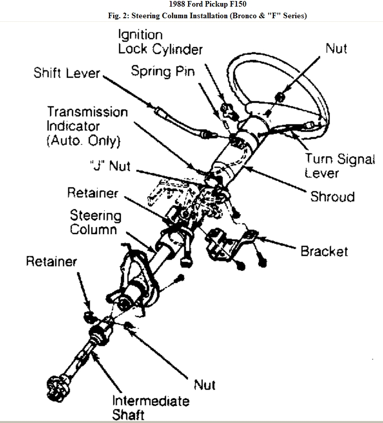
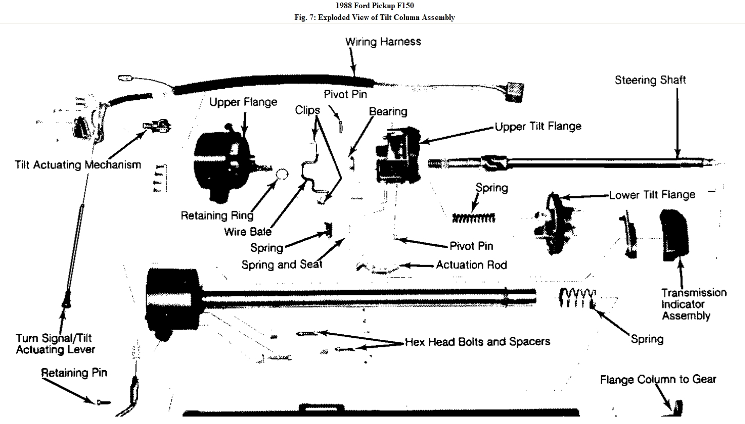
1. Remove steering wheel. Remove column from vehicle. Remove turn signal lever. Drive out
pivot pin. On column shift models, remove shift lever. On all models, remove lower flange and
retaining clamp.
2. Remove lower bearing retainer. On column shift models, remove shift tube retaining rivet from
bottom of shift socket. Withdraw shift tube from bottom of column.
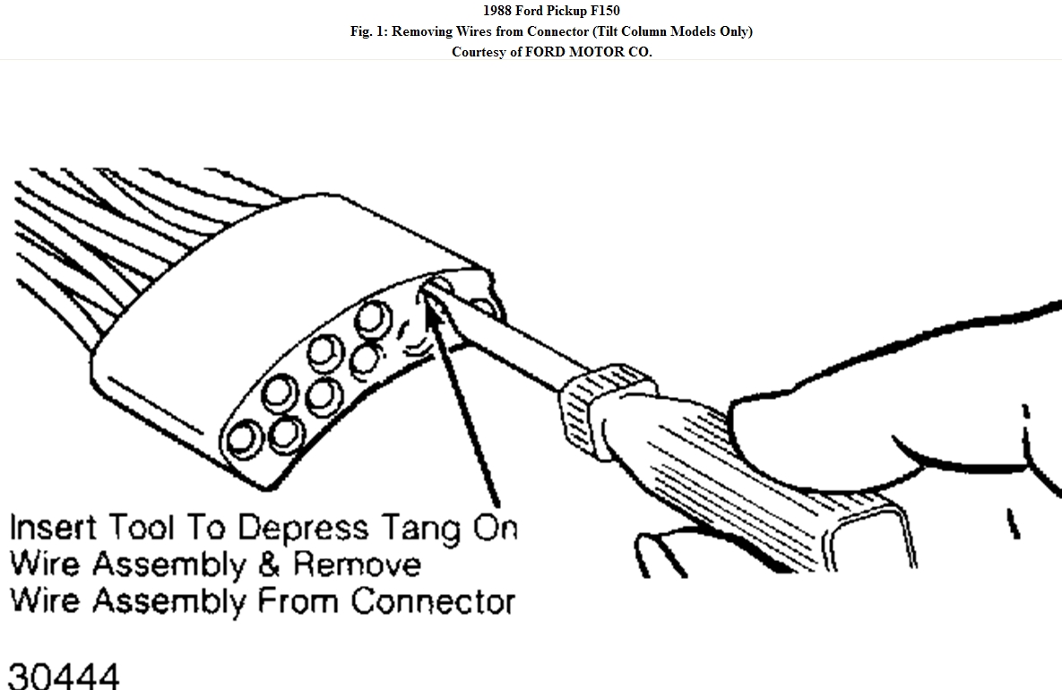
3. On all models, remove lock drive gear. Remove turn signal switch screws and wiring harness-
to-column retaining clips. Remove switch and wiring harness from column. Remove cover
casting screws. Remove casting from column.
4. Unhook upper actuator from lower actuator. Remove upper actuator. Remove lower flange-to-
outer tube attaching screws. Discard screws. Loosen ignition switch retaining screws. Remove
ignition actuator rod from switch.
5. Withdraw tilt mechanism, steering shaft and ignition actuator rod from steering column upper
end. On column shift models, remove shift socket. On floor shift models, remove flange
extension.
Fig. 7: Exploded View of Tilt Column Assembly
Reassembly

1. On A/T models, attach shift indicator ring to tilt mechanism. Install shift socket. On floor shift
models, attach flange extension and key release mechanism to tilt mechanism and tighten.
2. On all models, install tilt mechanism, feeding steering shaft down center of column and
ignition switch actuator rod through shift socket/flange extension along top of column outer
tube.
3. Using new hex screws, install 3 flange retainer assemblies and tighten. Install lower bearing
retainer. Attach ignition switch loosely to outer tube.
4. Connect upper and lower actuators. Install cover on column and tighten screws. Install turn
signal switch and wiring harness in column. Attach wiring harness-to-steering column clips.
5. Install 2 turn signal switch-to-flange casting attaching screws. Install one warning buzzer
terminal attaching screw and tighten screws. Install turn signal lever. Install lock drive gear.
With key in "ON" position, install lock cylinder. Install retaining pin flush with cylinder.
6. With ignition switch mounting nuts loose, clip switch through opening in side of switch
casting. Center switch on actuation rod. Tighten retaining nuts. Remove clip. Install shift lever
and pivot pin on A/T. Install turn signal lever. Install steering column and steering wheel.
FLANGE & LOCKING MECHANISM

NOTE:
Due to telescopic feature, care must be taken not to change
length of steering shaft.
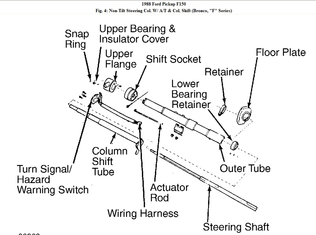
Disassembly (Non-Tilt Columns)

1. Remove flange retaining bolts. On M/T models, remove snap ring and spring from lock release
lever assembly. On A/T models, remove shift indicator insert from front of flange. On all
models, turn ignition on.
2. Depress retaining pin. Remove lock cylinder from flange. Remove lock bearing snap ring, lock
bearing, lock drive gear and actuator assembly. Remove lock actuator insert screw and lock
actuator through opening in front of flange.
Reassembly (Non-Tilt Columns)

1. Install lock actuator insert in rear of flange. Insert lock actuator assembly through opening in
front of flange until it bottoms against insert.
2. Install lock drive gear through lock cylinder opening so that last gear tooth aligns with last
tooth in actuator assembly when actuator is fully rearward.
3. Install lock bearing and snap ring. Turn ignition on. Depress retaining ring while inserting lock
cylinder into flange. On A/T models, attach shift indicator insert to front of flange.
4. On M/T models, position spring on lock release lever assembly through hole in front of flange.
Install snap ring on lock release lever assembly. On all models, install retaining bolt through
holes in flange. Finger tighten nuts from rear side.
Disassembly (Tilt Columns)

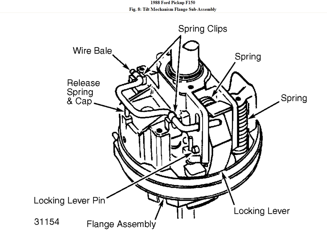
1. Remove steering column from vehicle. Remove spring clips holding wire bale. Lift off wire
bale. With a small drift, drive out locking lever retaining pin. See Fig. 8.
Fig. 8: Tilt Mechanism Flange Sub-Assembly
2. Remove lever and spring. Using a "C" clamp, relieve tension on pin (if necessary). Remove
column upper shaft snap ring. Separate upper and lower flange castings by removing 2 pivot
pins located in side of casting.
3. Using Pin Remover (T70P-3D739-A) and Pin Remover Handle (T67P-3D739-C), remove
pivot pins. Do not reuse pivot pins if press fit is loose in flange. By tapping lightly on outer
races of bearings, replace upper flange bearings.
Reassembly (Tilt Columns)

1. Install lower actuator with ignition switch rod attached. Assemble upper and lower flange.
Using a "C" clamp, press in pivot pins. Ensure column position spring is properly seated
between upper and lower flange.
2. Wavy thrust washer must be positioned between lower flange and socket. Install upper column
snap ring. Assemble locking lever, spring and lever pin. Install wire bale and spring clips.
Was this
answer
helpful?
Yes
No
+1
Tuesday, March 22nd, 2011 AT 7:43 PM
Tiny
CHIEFCW2
  • MEMBER
  • 7 POSTS
Thank You very much!
Was this
answer
helpful?
Yes
No
Thursday, March 24th, 2011 AT 10:18 AM
Tiny
MERLIN2021
  • MECHANIC
  • 17,250 POSTS
You bet.
Was this
answer
helpful?
Yes
No
Thursday, March 24th, 2011 AT 2:09 PM

Please login or register to post a reply.

Sponsored links