Can I get the Front Suspension Torque Specs?

Tiny
NORTHERN DAKOTA
  • MEMBER
  • 1987 DODGE DAKOTA
  • 3.7L
  • 6 CYL
  • 2WD
  • 100,000 MILES
I am completely rebuilding the front-end suspension of the vehicle listed above (2-wheel drive, V6 model), including a new rack and pinion and am looking for all the torque specs.
Sunday, January 29th, 2023 AT 11:57 AM

7 Replies

Tiny
CARADIODOC
  • MECHANIC
  • 33,744 POSTS
There's no chart or list provided for torque specs, so I looked up each part replacement procedure I could find. Those included some torque specs in the instructions. I put those together in these lists.

There's two things to consider when doing this job. First, we simply use common sense when tightening many of these parts. For example, there's no values given related to the anti-sway bar bushings and links. You won't cause a safety concern if those fasteners are not set to an exact spec. Bolts such as those for the bushing brackets use torque specs for the diameter of the bolt, but even those do not need to be tightened to their maximum values they can withstand.

Second, a common mistake to watch out for is when tightening any fastener for a bushing that pivots, that bushing must be at its "at-rest" orientation when doing the tightening. The only ones that apply here are the bushings for the upper and lower control arms. Those can be installed, but not tightened until the truck is let down off the jack stands and is sitting at normal ride height on the tires. Too many competent do-it-yourselfers, and even some inexperienced mechanics, will tighten those pivot bushings while the vehicle is up on a hoist or jack stands, with the suspension hanging down. If they're tightened at that time, when the truck is set down on the tires, those control arms pivot up to their "at-rest" position, clamping those bushings in a permanent twist. When driving over bumpy roads and the front of the truck drops down momentarily, the control arms pivot up, twisting those bushings much further than they are designed to go. That leads to early failure of those bushings.

If you're replacing inner tie rod ends, Chrysler never provided a torque spec for those. Failures were uncommon. If one needed to be replaced in the warranty period, Chrysler insisted the entire rack and pinion assembly must be replaced. They always came with the inner and outer tie rod ends already installed. When the truck is out of warranty, aftermarket inner tie rod ends can be replaced separately. They will come with a sheet of instructions that include the torque spec for the inner housing that screws onto the rack.

When torquing a castle nut for a ball joint stud, once you reach the desired value, continue tightening it until the first slot lines up with the cotter pin hole. Never back it off to get the cotter pin in.

Sometimes a replacement ball joint can fit multiple applications if a simple modification is made. Specifically, the stud may be a little too long on some models where the hole in the steering knuckle isn't deep enough. The stud will be of the correct taper to wedge tightly into place, but you'll find the cotter pin hole is up too high. The cotter pin will be up above the slots in the nut. When that is a possibility, the ball joint will come with a pair of large washers. Slip one or both of them just under the castle nut to make the slots at the same height as the cotter pin hole. Those instructions will be included on the sheet that comes with the joint. I've only seen that so far with lower ball joints, not uppers.

One more thing to be aware of that, to my knowledge, only applies to Dakotas and Durangos, had to do with inspecting the lower ball joints. Normally the vehicle must be supported in one of two ways to allow the lower ball joint to be "unloaded", meaning you can pry parts around to look for unallowable movement. We're looking for looseness between the ball and the socket it sits in. There must never be any sideways movement as that would allow the alignment to change while driving. It's also a good indication so much wear has taken place that those parts could separate, leading to loss of control and a crash. (Just ask any Ford owner. They know too much about that). Up and down movement between the ball and socket is also a sign of wear, and can cause a clunking noise on bumpy roads, ... Except on the Dakotas and Durangos. When you look at a new lower ball joint at the dealer's parts department, you'll find it already has a good 1/8" of up and down play built in. You don't have to tug on it or put pressure on it. That play is very easy to see, and most people incorrectly assume it is defective.

Aftermarket replacement lower ball joints do not come with that play built in. My question then, at a training class, was if I'm inspecting the steering and suspension system on a Dakota, and I see that up and down play, how do I know if it's a good original joint or a worn aftermarket replacement? The answer made perfect sense. An aftermarket replacement lower ball joint can be allowed to develop that 1/8" of up and down play, and still be considered safe. As with all other models, it can never be allowed to have sideways movement. This was common in the '90s. I can't remember if it applies to mid '80s models, but if you run into that 1/8" of play, consider that normal and acceptable.

Let me know how this turns out, and if you need other information. This is the time to check suspension ride height and replace the coil springs if necessary. I have a simple trick for doing that which removes the safety concern and can turn it into a one-man job.
Was this
answer
helpful?
Yes
No
+1
Sunday, January 29th, 2023 AT 2:59 PM
Tiny
NORTHERN DAKOTA
  • MEMBER
  • 6 POSTS
Thank you very much for all this info! :-)
When tightening the Pivot Bar Retaining Nuts, I notice there is some play in the slots of the mounting bracket. Should I torque it down once the assembly is complete, or can I tighten it first?
I was aware to only tighten/torque the upper & lower table bushings when the vehicle was in the "at rest" position, thanks! ;-)

Yes, I am also replacing the coil springs, and am having a heck of a time trying to figure out how I can compress them to get them installed. I had the "outside" style spring compressors, but there's not enough room to use them, and I just bought the one that goes through the middle of the coil but for the life of me I can't see how to get it to compress the coil evenly. Any advise/tips would be greatly appreciated!

The only original components are the lower tables that I completely unassembled, sand blasted and had powder coated after having them welded up where needed. I would have gladly bought new ones, but after weeks of searching for them, gave up. All other components and most nuts & bolts are all new, including a rebuilt rack & pinion.

FYI, the 1987 Dakota frame is currently hosting a 1941 Ford Tudor, with a small block V8.
Was this
answer
helpful?
Yes
No
Sunday, January 29th, 2023 AT 6:00 PM
Tiny
CARADIODOC
  • MECHANIC
  • 33,744 POSTS
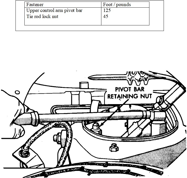
Dandy. Those slotted holes for the upper control arm's bolts are alignment adjustments. I strongly recommend you use no grease or any type of lubricant on those slides. If those two bolts don't clamp hard enough, the alignment can shift when you hit bumps in the road. Your alignment specialist will tighten those bolts when he's done with those adjustments.

Both of those corners of the upper control arm are pushed in or pulled out to adjust "camber". That's the inward or outward tilt of the wheel, as viewed from in front of the truck. One is pulled out and the other is pushed in to adjust "caster". That moves the upper ball joint forward or rearward relative to the lower ball joint.

99% of vehicles call for slightly positive camber, meaning the wheel is tipped out on top. That results in best tire wear and it places the truck's weight right over the larger "load-carrying" wheel bearing. The job of the smaller wheel bearing is just to hold the wheel straight. Tires want to roll in the direction they're leaning, so besides being in specs, both must be very close to equal, so their pulls will offset each other, then the left one should be just a little higher positive to offset "road crown". That's the slant of the road surface to the right so water runs off.

Caster is responsible for how quickly the steering wheel returns to center on its own after you turn a corner. It is also responsible for reducing steering wander. Caster increases as the upper ball joint is moved further rearward. `Positive caster is when the upper ball joint is further back than the lower one. The higher caster is, the harder that wheel wants to turn toward the center of the truck. That can be hard enough that you can't pull that wheel back by hand. The other wheel also wants to turn in when vehicle weight is placed on it. It's when the steering linkage connects the two wheels together that the two forces offset each other. It is important that caster is also equal on both sides so their pulls offset each other. It can also be used to offset road crown.

It's very easy to adjust camber to specs on the first wheel, and take what you get for caster when it is "close enough". Camber is a major tire wear angle. Caster has no effect on tire wear for all practical purposes, but I have to add a comment here for the benefit of others preparing to take the Suspension and Alignment certification test. In their opinion, caster IS a tire wear angle. The problem is caster wear only takes place when you're turning a corner. That applies to city driving and when in a parking lot. In reality, no tire will ever wear out or have excessive wear due to misadjusted caster.

Adjusting the second wheel is trickier. Camber still has to be set to specs, but it takes considerable jockeying back and forth to match caster on both sides. This is where the most time is spent getting everything right.

Due to the geometric relationship of the steering and suspension parts, readjusting caster and camber causes a change in "toe". That's the direction the wheels are steering. Readjusting toe has no noticeable effect on camber and caster measurements, so toe is always the last thing to be adjusted during the alignment. "Total toe", the sum of toe on the two wheels, is also a major tire wear angle.

For a couple of months in the mid '90s, every full-size Dodge van came off the assembly line with front coil springs one spring rate too light. I was involved in a recall where those springs had to be replaced with the correct ones. To add to the misery, I had to do them on a drive-on alignment hoist. Thanks to previous experience, I was able to do the pair in about 20 minutes. The secret is to leave the lower ball joint connected, and if you have a helper, you don't even have to remove the wheel and tire.

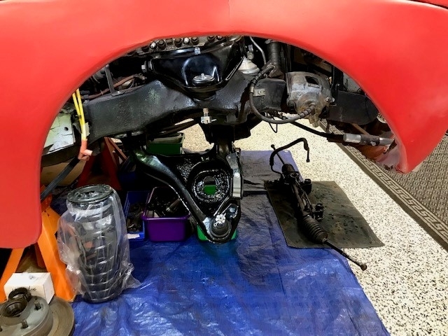
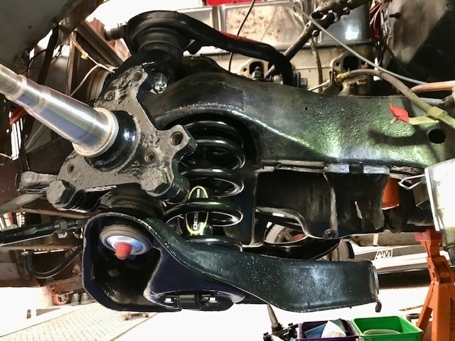
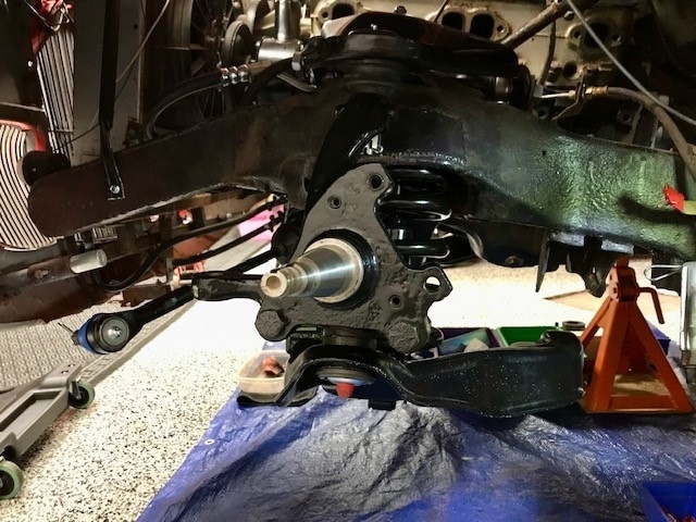
Raise the truck up and support it on jack stands or hoist arms under the frame so the suspension hangs down freely. If you're doing this on your garage floor, place a floor jack under the inner edge of the lower control arm, between the two pivot bolts. Remove those two pivot bolts, then let the jack down. All pressure will be off the spring once the arm comes down about four inches. Have your helper pull out on the bottom of the tire, or, if you have the wheel off already, just pull the lower arm down and lift the spring out.

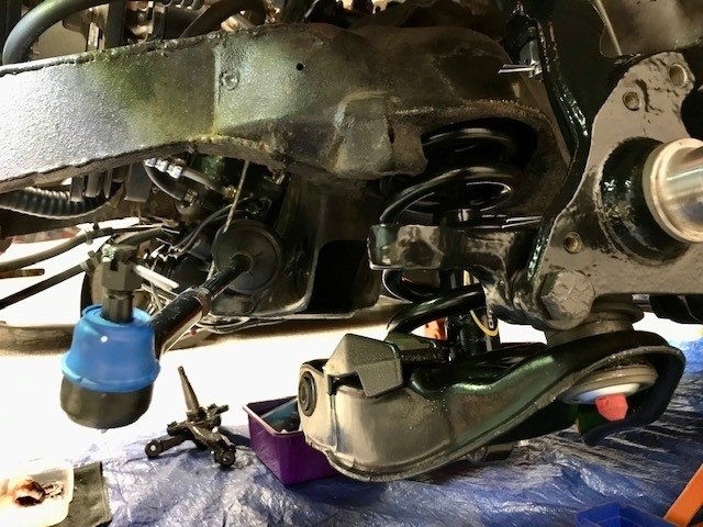
If you're not doing other work, as you did, on the arm, clean out any dirt or pebbles from the pocket the spring sits in. Those pebbles can cause a temporary crunching noise, and they will scrub off the protective coating on the new spring. The lower end of the spring must be indexed to sit squarely in the matching pocket in the arm. Don't worry about where the upper end of the coil ends up. It's flat and will sit just fine on its mounting surface. Often there's a rubber isolator on top of the spring. Use string or speaker wire to tie it to the spring so it doesn't fall off during spring installation. This job is easier if the anti-sway bar link is removed.

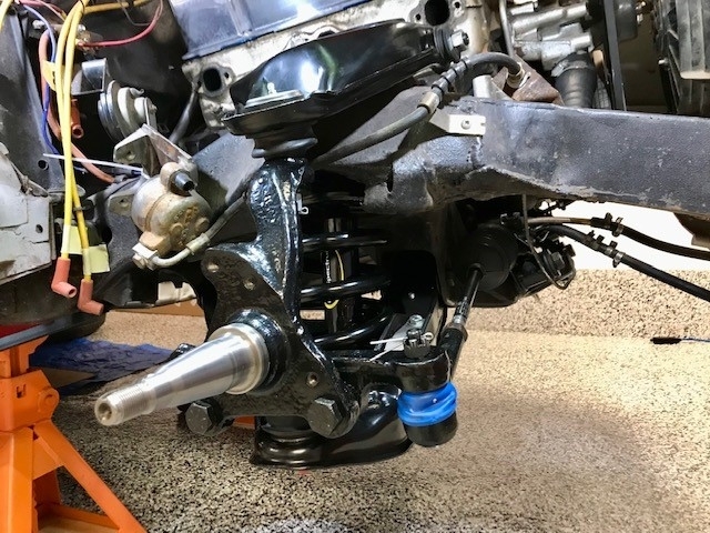
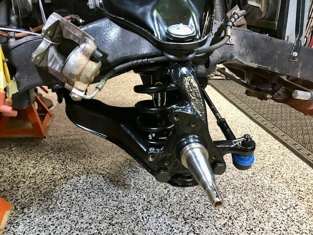
Now raise the jack to push the arm back up. You'll need a pry bar to shift it around so the bushings slide into place. Once one bushing gets close, you'll be very lucky if you can slide the pivot bolt in. Instead, use a tapered bar or "line-up" tool, or even a large screwdriver through the holes to hold that bushing in place. Now work the second bushing into place. When both are close, you'll find it rather easy to fine tune one bushing so the bolt can be inserted. At that point the arm is captive and can't squirt out. Work the second pivot bolt in. When both springs are done, set the truck down on the tires, bounce it a few times or drive it around the parking lot to settle the suspension, then crawl underneath to tighten the pivot bolts while the truck is sitting at normal ride height.

Let me know how that works for you.
Was this
answer
helpful?
Yes
No
+1
Monday, January 30th, 2023 AT 11:11 AM
Tiny
NORTHERN DAKOTA
  • MEMBER
  • 6 POSTS
I've reassembled the lower table on driver side, installed the upper and lower ball joint and the shock, per the attached photos. However, when I jack up the table the rear arm (smaller bushing) goes up into place, but the front arm (larger bushing) only goes in partially before it jams. I can get a pry bar into the rear hole of the small bushing, but as it is on an angle, I can't get the bolt through. Can I leave the pry bar like this, lower the jack and reposition it under the front arm (larger bushing) and jack it up into place?
Was this
answer
helpful?
Yes
No
Tuesday, January 31st, 2023 AT 7:03 PM
Tiny
CARADIODOC
  • MECHANIC
  • 33,744 POSTS
Absolutely, the first bar will hold that bushing close, then you can lower and reposition the jack as needed. Being on a drive-on hoist, I had to use a "post jack". Think of a bottle jack, but it starts out about three feet tall, and it had legs with wheels. I had to drive those vans all the way to one side of the hoist to do the spring on one side, then move the van over to the other side of the hoist to do the second spring. It was actually easier because instead of needing a helper to tug out on the bottoms of the tires, I just let the jacks on the hoist down and as the van came down, the tires squirted out on its own. Was rather easy to lift the spring out once the lower arm dropped down.

There can be some frustration in getting the bushings to slide into place. The trick is to get both very close and lined up, then jack the arm up. If only one bushing goes in first, they will both be at too steep of an angle to fit into their brackets.

Also consider lifting one corner of the arm up to the bottom of its bracket, then stacking blocks of wood under it. With that holding up that corner, you're free to move the jack to the other corner. This job gets a lot easier the more you do it.
Was this
answer
helpful?
Yes
No
+1
Tuesday, January 31st, 2023 AT 10:05 PM
Tiny
NORTHERN DAKOTA
  • MEMBER
  • 6 POSTS
I just wanted to say thank you very much for the help. With your advise and guidance, I got the job done! ;-)
Was this
answer
helpful?
Yes
No
Wednesday, February 1st, 2023 AT 3:28 PM
Tiny
CARADIODOC
  • MECHANIC
  • 33,744 POSTS
Dandy news. I knew you could do it.

Please come back to see us with your next project.
Was this
answer
helpful?
Yes
No
Wednesday, February 1st, 2023 AT 4:06 PM

Please login or register to post a reply.

Sponsored links