Hello -
Okay, you have some checks to do and you should be okay. . .. . .. . ...
P1135
INT/V TIM CONT-B2 Intake Valve Timing Control - Right Bank
Description
The mechanism hydraulically controls cam phases continuously with the fixed operating angle of the intake valve. The ECM receives signals such as crankshaft position, camshaft position, engine speed, and engine coolant temperature. Then, the ECM sends on/off pulse duty signals to the IVTC solenoid valve depending on driving status. This makes it possible to control the shut/open timing of the intake valve to increase engine torque in low/mid speed range and output in high-speed range.
Possible Causes
Malfunction is detected when
A. The alignment of the intake valve timing control has been misregistered.
B. There is a gap between angle of target and phase-control angle degree.
When malfunction "A" or "B" is detected, the ECM enters fail-safe mode. MIL will illuminate, and ECM will not energize IVTC solenoid valve, and system will not function.
Possible causes are:
"� IVTC position sensor circuit open or shorted.
"� Defective IVTC position sensor.
"� Defective crankshaft position sensor (POS).
"� Defective camshaft position sensor (PHASE).
"� Accumulation of debris to signal pickup area of camshaft.
Diagnostic Procedure
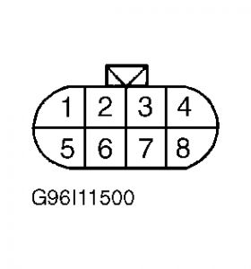
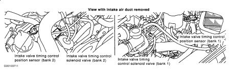
1. Turn ignition off. Disconnect appropriate IVTC position sensor harness connector. See Fig. 54 . Turn ignition on. Measure voltage between ground and IVTC position sensor harness connector terminal No. 3 (Green/Yellow wire). If battery voltage exists, go to step 3 . If battery voltage does not exist, go to next step.

2. Check the following:
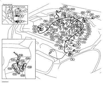
"� Check for poor connection at connector F32 terminal No. 4 (Green/Yellow wire). See Fig. 15 and Fig. 35 .

"� Check for poor connection at fuse, fusible link and relay block harness connector E3 terminal 34R (Green/Yellow wire). See Fig. 11 .
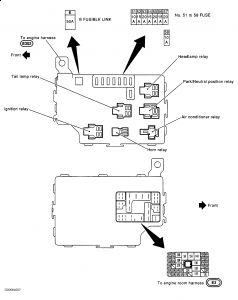
"� Check fuse No. 58 (10-amp) located in fuse, fusible link and relay block on right side of engine compartment.
"� Check for open or short between IVTC position sensor and fuse.
Repair as necessary.
3. Turn ignition off. Check continuity between engine ground and IVTC position sensor harness connector terminal No. 1 (Black/Yellow wire). Continuity should exist. Also, check circuit for short to voltage. If problem is found, go to next step. If circuit is okay, go to step 5 .
4. Check the following:
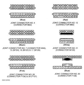
"� Check joint connector No. 29 (connector F107). See Fig. 15 and Fig. 19 .

"� Check for open or short between engine ground and IVTC position sensor. See Q45 in WIRING DIAGRAMS article.
Repair as necessary.
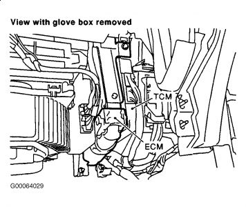
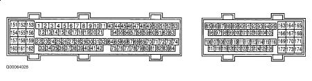
5. Disconnect ECM harness connector. See Fig. 5 . Check continuity of Yellow wire between left IVTC solenoid harness connector terminal No. 2 and ECM harness connector terminal No. 73, or White wire between right IVTC solenoid harness connector terminal No. 2 and ECM harness connector terminal No. 74. See Fig. 8 . Also, check circuit for short to ground and short to voltage. If problem is found, repair as necessary. If circuit is okay, go to next step.
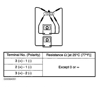
6. Remove IVTC position sensor. Visually inspect sensor for chipping. Measure resistance of sensor as shown in illustration. See Fig. 43 . If resistance is as specified and sensor is not chipped, go to next step. If resistance is not as specified or sensor is chipped, replace IVTC position sensor.
7. Check CKP sensor (POS). See step 7 under DIAGNOSTIC PROCEDURE under DTC P0335 OR P1336: CRANKSHAFT POSITION SENSOR (POS). If sensor is okay, go to next step. If sensor is not okay, replace CKP sensor (POS).
8. Check CMP sensor (PHASE). See step 7 under DIAGNOSTIC PROCEDURE under DTC P0340: CAMSHAFT POSITION SENSOR (PHASE). If sensor is okay, go to next step. If sensor is not okay, replace CMP sensor (PHASE).
9. Check for accumulation of debris on signal pick-up portion of camshaft. Remove debris and clean camshaft as necessary. If accumulation of debris is not present, go to next step.
10. Disconnect joint connectors No. 28 (connector F106) and No. 29 (connector F107) located under right side of instrument panel. See Fig. 15 and Fig. 19 . Check the following:


"� Check continuity of shield circuit (Gray wire) between joint connector No. 28 terminals No. 1 and 3.
"� Check continuity of shield circuit (Gray wire) between joint connector No. 28 terminal No. 3 and joint connector No. 29 terminal No. 3.
"� Check continuity between ground and shield circuit (Gray wire) at joint connector No. 29 terminal No. 3.
"� Check joint connectors No. 28 and 29.
Continuity should exist. Also, check circuit for short to voltage. If problem is found, repair as necessary. If circuit is okay, go to next step.
11. No problem is indicated at this time. Problem may be intermittent. See INTERMITTENTS in TROUBLE SHOOTING - NO CODES article.
P1145
INTK TIM S/CIRC-B2 Intake Valve Timing Control Position Sensor (Circuit) - Right Bank
Possible Causes
Malfunction is detected when an excessively high or low voltage from the sensor is sent to ECM. Possible causes are:
"� IVTC position sensor circuit open or shorted.
"� Defective IVTC position sensor.
"� Defective crankshaft position sensor (POS).
"� Defective camshaft position sensor (PHASE).
"� Accumulation of debris on signal pick-up portion of camshaft.
Diagnostic Procedure
1. Turn ignition off. Disconnect appropriate IVTC position sensor harness connector. See Fig. 54 . Turn ignition on. Measure voltage between ground and appropriate IVTC position sensor harness connector terminal No. 3 (Green/Yellow wire). If battery voltage exists, go to step 3 . If battery voltage does not exist, go to next step.
2. Check the following:
"� Check for poor connection at connector F32 terminal No. 4 (Green/Yellow wire). See Fig. 15 and Fig. 35 .


"� Check fuse No. 58 (10-amp) located in fuse, fusible link and relay block on right side of engine compartment.
"� Check for poor connection at fuse, fusible link and relay block connector E3 terminal 34R (Green/Yellow wire). See Fig. 11 .

"� Check for open or short between appropriate IVTC position sensor and fuse.
Repair as necessary.
3. Turn ignition off. Check continuity between engine ground and appropriate IVTC position sensor harness connector terminal No. 1 (Black/Yellow wire). Continuity should exist. Also, check circuit for short to voltage. If problem is found, go to next step. If circuit is okay, go to step 5 .
4. Check the following:
"� Check joint connector No. 29 (connector F107) located under right side of instrument panel. See Fig. 15 and Fig. 19 .

"� Check for open or short between engine ground and IVTC position sensor.
Repair as necessary.
5. Disconnect ECM harness connector. See Fig. 5 . Check continuity of Yellow wire between left IVTC position sensor harness connector terminal No. 2 and ECM harness connector terminal No. 73, or White wire between right IVTC position sensor harness connector terminal No. 2 and ECM harness connector terminal No. 74. See Fig. 8 . Also, check circuit for short to ground and short to voltage. If problem is found, repair as necessary. If circuit is okay, go to next step.


6. Remove IVTC position sensor. Visually inspect sensor for chipping. Measure resistance of sensor as shown in illustration. See Fig. 43 . If resistance is as specified and sensor is not chipped, go to next step. If resistance is not as specified or sensor is chipped, replace IVTC position sensor.

7. Check CKP sensor (POS). See step 7 under DIAGNOSTIC PROCEDURE under DTC P0335 OR P1336: CRANKSHAFT POSITION SENSOR (POS). If sensor is okay, go to next step. If sensor is not okay, replace CKP sensor (POS).
8. Check CMP sensor (PHASE). See step 7 under DIAGNOSTIC PROCEDURE under DTC P0340: CAMSHAFT POSITION SENSOR (PHASE). If sensor is okay, go to next step. If sensor is not okay, replace CMP sensor (PHASE).
9. Check for accumulation of debris on signal pick-up portion of camshaft. Remove debris and clean camshaft as necessary. If accumulation of debris is not present, go to next step.
10. Disconnect joint connectors No. 28 (connector F106) and No. 29 (connector F107) located under right side of instrument panel. See Fig. 15 and Fig. 19 . Check the following:


"� Check continuity of shield circuit (Gray wire) between joint connector No. 28 terminals No. 1 and 3.
"� Check continuity of shield circuit (Gray wire) between joint connector No. 28 terminal No. 3 and joint connector No. 29 terminal No. 3.
"� Check continuity between ground and shield circuit (Gray wire) at joint connector No. 29 terminal No. 3.
"� Check joint connectors No. 28 and 29.
Continuity should exist. Also, check circuit for short to voltage. If problem is found, repair as necessary. If circuit is okay, go to next step.
11. No problem is indicated at this time. Problem may be intermittent. See INTERMITTENTS in TROUBLE SHOOTING - NO CODES article.
Looks like the checks are the same. . .. . .. . .. . .. . .
If you don't want to do all the checks. . .. . .you could take a chance and change the sensors. . .
The IVTC, crankshaft and camshaft. . .. . .. . .. . .
Then go to AZ and have them clear the codes and try it again.
Monday, September 28th, 2009 AT 5:49 AM