Okay, I attached the codes below. I do not see anything in the codes for your issue.
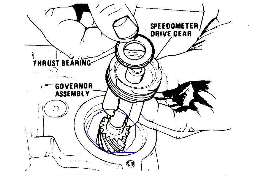
I would suggest the governor may be the fault.I attached the procedure and a picture. The gear I circled is the common failure.
Roy
52
Code 52 indicates that the ``long term'' memory in the ECM has been reset. This will occur whenever power is removed from the ECM. The code should be cleared from the memory after restoring the ECM's power supply. When the ``prom error'' is corrected, the ECM resets its memory and stores code 52.
19
With ignition on, ECM energizes fuel pump relay for two seconds and feeds 12 volts to fuel pump circuit. Unless distributor reference pulses are received within this time, ECM will de-energize relay so that fuel pump will not continue to run with ignition on. Code 19 indicates that fuel pump relay circuit continues to have 12 volts after two second prime. Possible causes of this condition are:
a. Faulty fuel pump relay.
B. Faulty oil pressure switch.
C. Defective wiring harness or electrical connectors.
D. ECM not processing fuel pump signal or not turning relay off.
To diagnose a Code 19, proceed as follows:
1. If unwanted source of voltage can be eliminated, self-diagnostics can be used to detect this by displaying parameter.1.0. When voltage is removed from circuit, ``battery voltage'' reading will drop to 0 volts.
2. Eliminate branches of fuel pump circuit first by removing oil pressure switch connector. If ``battery voltage'' reading is now 0, oil pressure switch must be replaced because it is closing switch without receiving oil pressure.
3. If ``battery voltage'' reading is still greater than 0 volts, another portion of fuel pump circuit can be eliminated by removing fuel pump relay.
4. If ``battery voltage'' reading is still greater than 0 volts, inspect circuits 120 and 120E for a short to voltage.
5. If voltage on circuit 120 is greater than 0 volts when ECM is disconnected, the circuit is shorted to voltage. If voltage reading is 0, fault must be in ECM connector or in ECM.
6. If ``battery voltage'' reading is now 0 after removing fuel pump relay, probe relay socket cavity 5 with a test lamp to ground. With ignition on, test lamp should light for two seconds, then go out. If light goes out, replace relay.
7. If light stays on, either ECM or wiring harness is shorted to voltage. If there is voltage on circuit 465 with ECM disconnected, circuit is shorted to voltage. If voltage is 0, check for faulty ECM or ECM connector.
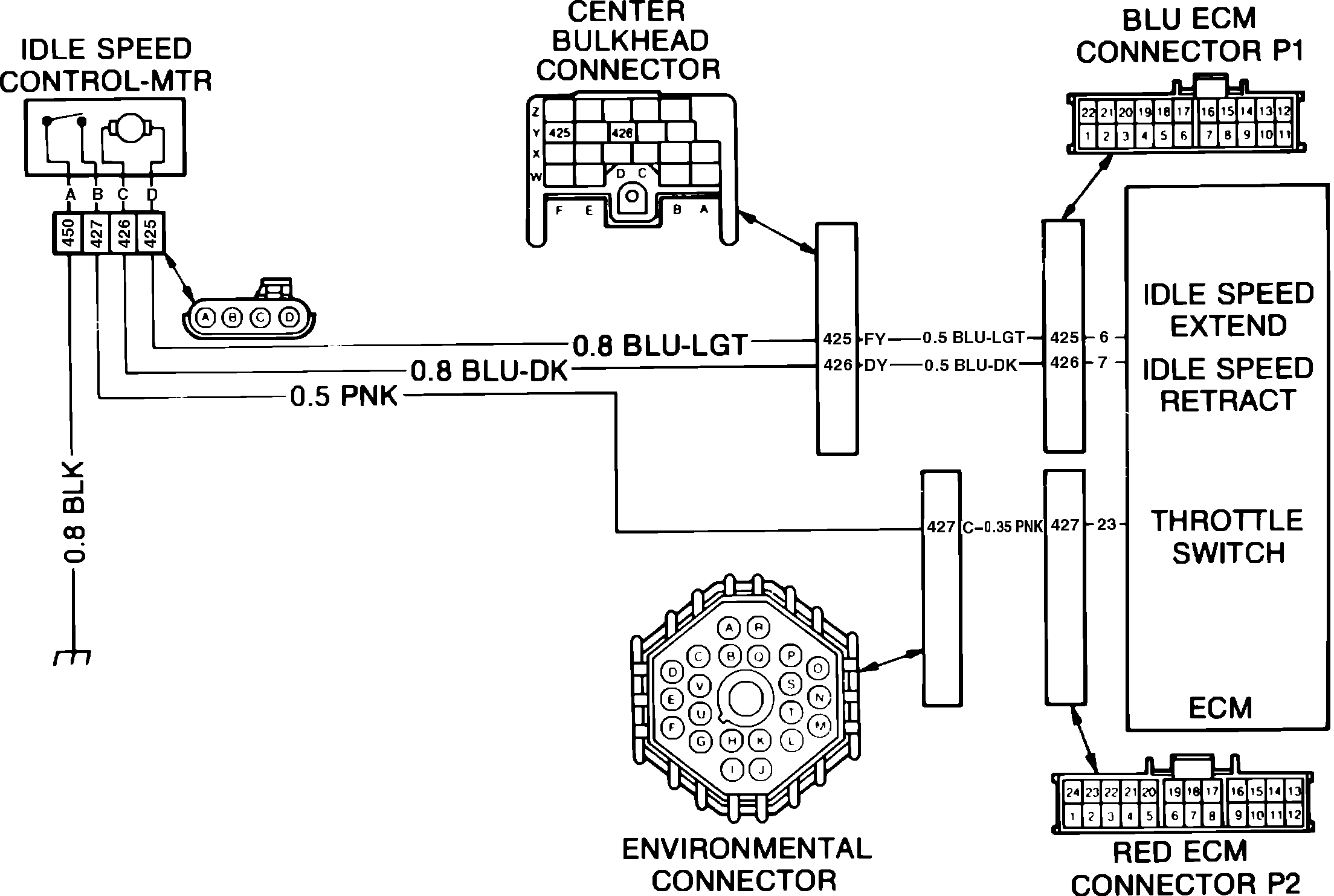
27
If this code is not displayed during the third pass of diagnostic codes, the problem is an intermittent failure. To help isolate the problem, operate vehicle while observing throttle switch status light. If throttle switch ever fails to close upon release of throttle, investigate circuit for malfunction. Also check for misadjusted minimum air rate, binding throttle linkage or binding ISC plunger.
The ECM supplies a 5 volt signal to pin B of the idle speed control motor. When the engine operates above idle speed, the throttle switch is open and the ECM increases voltage in circuit 427 to 5 volts. When the idle speed switch is open, the idle speed control motor will not control idle speed because engine speed is controlled by the driver. Code 27 indicates that the throttle switch remained open during the last ignition cycle and has not yet closed during the present cycle. Possible causes of this condition are:
a. Defective idle switch.
B. Defective wiring or electrical connectors.
C. ECM unable to process signals properly.
To diagnose a Code 27, proceed as follows:
1. Turn ignition on and enter diagnostics. Observe ``Throttle Switch'' light above ``Lo'' button on ECC control head. If light comes on, proceed to step 2. If light remains off, refer to ``Code.7.2, Throttle Switch Circuit'' diagnosis.
2. Exit diagnostics with ``Throttle Switch'' light on. If Code 27 remains as a hard code, replace ECM. If Code 27 is now an intermittent, refer to note above.
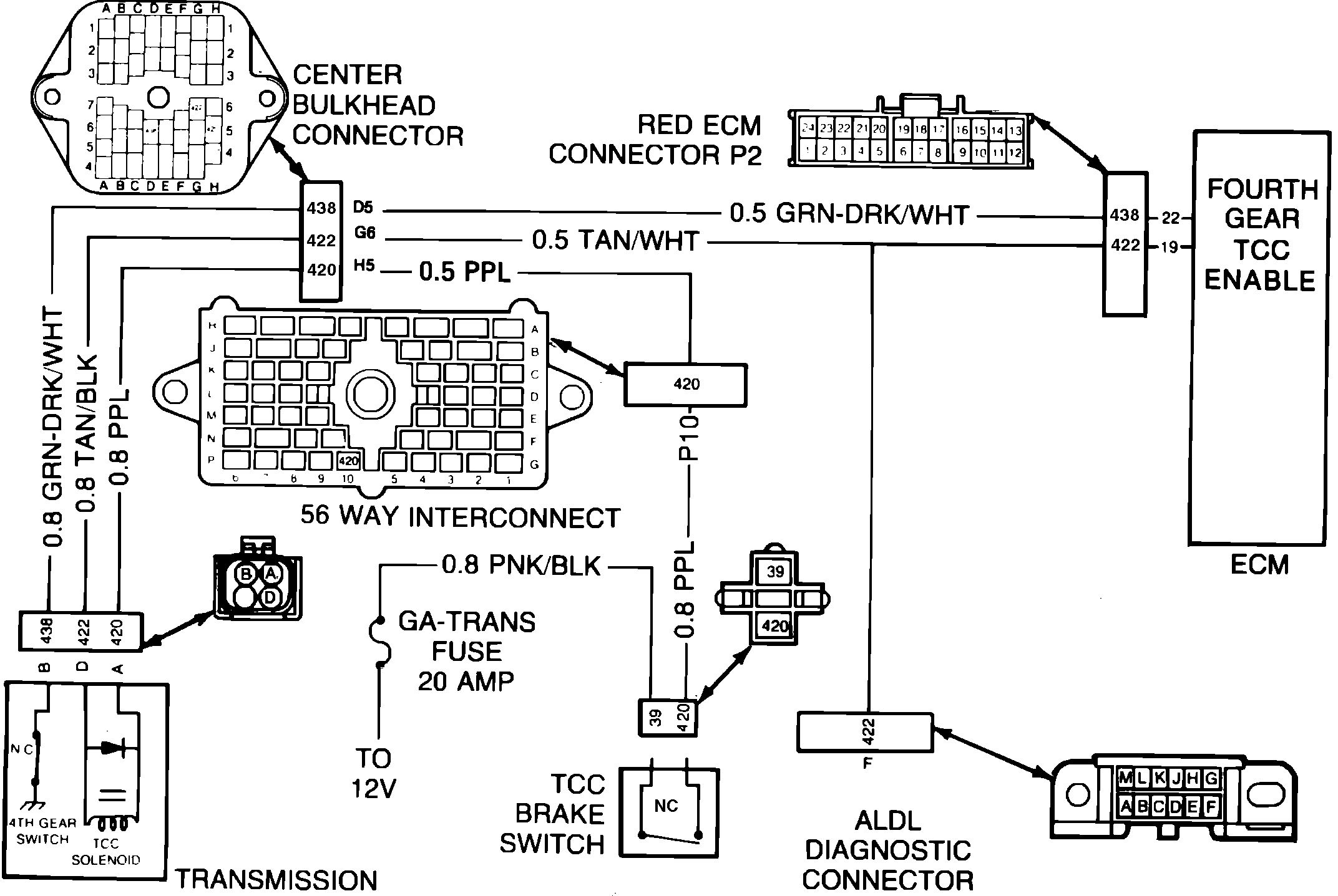
39
The ECM completes circuit for TCC solenoid by grounding circuit 422. Grounding this circuit allows solenoid to energize and supply oil pressure to torque converter clutch. Code 39 indicates that ECM is seeing engine speed at a greater RPM than would be expected at 55 mph with TCC engaged. Possible causes of this condition are:
a. Defective TCC solenoid.
B. Defective TCC brake switch.
C. Defective wiring or electrical connectors.
D. ECM not able to properly process signals.
To diagnose a Code 39, proceed as follows:
1. Turn ignition on and connect test lamp between ALDL diagnostic connector pin F and ground.
2. If test lamp lights, proceed to step 3. If test lamp does not light, proceed as follows:
a. With ignition on and brakes released, check for voltage at both sides of TCC brake switch using a test lamp.
B. If test lamp does not light on either side of switch, check GA-TRANS fuse. If fuse is blown, replace fuse and repair ground in circuits fed by fuse. If fuse is not blown, repair open in circuit 3 or 39.
C. If test lamp lights on one side of switch only, check adjustment of TCC brake switch and adjust or replace as necessary.
D. If test lamp lights on both sides of switch, disconnect transmission connector and connect test lamp between pin A and ground. If test lamp lights, proceed to step 2e. If test lamp does not light, repair open in circuit 420.
E. Connect test lamp between pins A and D of harness connector. If lamp does not light, repair open in circuit 422. If lamp remains lit, check for loose transmission connector or open circuit in transmission.
3. If test lamp lights, proceed as follows:
a. Enter diagnostics and display Code.9.6. If test lamp remains lit, proceed to step 3b. If test lamp flashes in three second intervals, proceed to step 3d.
B. Disconnect transmission connector and measure resistance between pins A and D on transmission side of connector.
C. If measured resistance is less than 15 ohms, repair short in transmission circuit and verify that ECM has not been damaged. If resistance is greater than 15 ohms, check circuit 422 for an open. If circuit is satisfactory, check for faulty ECM or ECM connector and repair or replace as necessary.
D. Start engine, enter diagnostics and display parameter.1.2.
E. Drive vehicle at 55 mph. When TCC engages, the ``TCC'' status light will go on and test lamp will go out.
F. With test lamp off, display parameter.1.1 and ensure engine RPM does not exceed the following speeds at 55 mph: Eldorado and Seville except high altitude models, 1600; high altitude Eldorado and Seville, 1700; DeVille and Brougham except high altitude models, 1700; high altitude DeVille and Brougham, 1850.
G. If engine speed exceeds specifications, system is functioning normally and transmission is at fault.
Governor
Inspection
1. Remove drive gear from shaft, then inspect gear for damage or nicks.
2. Inspect governor cover for damage.
3. Inspect driven gear for nicks or damage.
4. Inspect governor shaft seal ring for cuts, damage and free fit in groove.
5. Inspect governor weights for free operation.
6. Inspect for damaged, mispositioned or tilted springs.
7. Inspect for presence of 2 check balls.
8. Inspect shaft for damage.
9. Inspect governor thrust washer for damage.
10. If damaged, remove seal ring by cutting it off governor shaft. Use care to avoid damaging groove.
Assembly & Installation
1. If removed, install seal ring on shaft and place seal ring end into pilot hole in case to size seal, then lubricate with petroleum jelly.
2. Install speedometer drive gear on governor shaft. Make sure that slot in gear aligns with pin in shaft.
ImageOpen In New TabZoom/Print
3. Install speedometer drive gear to governor cover-thrust washer, see image, then install governor and speedometer drive gear assembly into transmission case.
4. Install O-ring seal on governor cover, then install cover, making sure governor shaft aligns with hole in cover.
5. Install governor cover attaching bolts and torque to specifications.
6. Install speedometer driven gear assembly, bolt and retainer clip. Torque bolt to specifications.
Image (Click to make bigger)
SPONSORED LINKS
Saturday, July 11th, 2020 AT 10:39 AM
(Merged)