Timing chain guides?

Tiny
STRAYPONY
  • MEMBER
  • 2006 PONTIAC GRAND PRIX
  • 6 CYL
  • 2WD
  • AUTOMATIC
  • 60,000 MILES
My pontiac has what sounds like an electric engine whine coming from under the hood. It's pretty constant, but increases when I turn or when I step on the gas.

I'm fairly sure it's the guides on the timing chain. I had one replaced that was really making a lot of noise.

This noise is very distracting and annoying. Is there a way to get rid of it?

Is there a way to add extra noise buffers under the hood so I can't hear it?

In all other ways, I'm very pleased with my car. I've owned it for a year now.
Monday, April 27th, 2009 AT 4:20 PM

8 Replies

Tiny
MMPRINCE4000
  • MECHANIC
  • 8,549 POSTS
To be honest, i am somewhat confused,

Is this the 3800 V6? It uses a timing chain, not a belt.

The timing set consists of the crank gear/cam gear and chain. If noisy, replace the timing set.

But you should also look at PS pump for leaks, serpentine belt tensioner, serpentine belt for abnormal wear.

It would be abnormal for a timing chain to be bad this early on a car this new.

What exactly did the mechanic replace?

Tiiming set:


https://www.2carpros.com/forum/automotive_pictures/108325_GP_timing_chain_1.jpg


Chain dampner:


https://www.2carpros.com/forum/automotive_pictures/108325_GP_dampner_1.jpg

Was this
answer
helpful?
Yes
No
Wednesday, April 29th, 2009 AT 12:07 PM
Tiny
MOTOKING_1990
  • MEMBER
  • 10 POSTS
  • 1991 PONTIAC GRAND PRIX
  • 6 CYL
  • FWD
  • AUTOMATIC
  • 99,000 MILES
Can someone please enlighten me on how to do this! I used alldata but it didn't help too much! This is what I did the first time. Got every thing apart, took number one cylinder plug out cause couldn't find crank shaft tdc mark put a 1/4 extension in the hole rotated the crank til number one was all the way at the top. Turned all four cams til flats on camshaft where all up installed cam holding tool onto both heads. Put belt on counter clockwise position. Turned screw on the back of timing tensioner actuator til fully in put paper clip in hole to hold the actuator in. Put new oil in tensioner. Installed tensioner pulled paper clip and the actuator engaged into tensioner pulley. The original timing marks where still on there from factory and the two front cam marks where opposing and the two rear cam marks where towards each other, checked with straight edge! Rotated engine 3 revolutions still dead on. Put the car together started it. It backfired through intake I believe (couldn't really tell I was in the car) when it first cranked over. Then it started and sounds wrong for sure! So I took it back apart til I figure it out right this time. Idk if the timing marks where wrong or if it wasn't on tdc idk someone please help! A step by step or video would be helpful!
Was this
answer
helpful?
Yes
No
Wednesday, October 7th, 2020 AT 11:47 AM (Merged)
Tiny
BMRFIXIT
  • MECHANIC
  • 19,053 POSTS
This is what i have on ONDEMAND1

TIMING BELT NOTE:The camshaft timing procedure has been updated by TSB bulletin No. 47-61-34, dated December, 1994. Removal Disconnect negative battery cable. Remove air cleaner and duct assembly. Drain engine coolant. Remove accelerator and cruise control cables from throttle body. Remove fuel rail cover. Relieve fuel pressure. Remove fuel lines from fuel rail. Remove fuel mounting bracket. Remove heater hose and bracket from lower intake manifold. Remove PCV valve and vacuum line from throttle body. Remove electrical connectors from EGR valve, canister purge solenoid and MAP sensor. Remove EGR valve, and position aside. Remove vacuum lines from upper intake manifold tee. Remove wiring loom bracket for rear spark plug wires. Remove upper intake manifold. Remove coolant recovery tank. Remove serpentine drive belt and drive belt tensioner. Siphon fluid from power steering pump. Disconnect power steering lines and remove power steering pump. On 1991-93 vehicles only, reposition Powertrain Control Module (PCM) out of way. Remove PCM mounting bracket. On 1994-95 vehicles only, disconnect PCM connectors and secure out of way. On all vehicles, note position for reassembly reference and remove spark plug wires from spark plugs. Remove wiring harness cover at right side (passenger) strut tower. Remove fuel line bracket. Remove timing belt covers. Remove breather hose from rear camshaft cover and crankcase vent from breather manifold. Remove camshaft carrier covers. .

NOTE:Actuator assembly uses a tapered bushing between the actuator and mounting base. DO NOT lose or damage the bushing when removing the actuator assembly.

Remove side plate bolts securing timing belt tensioner actuator. Rotate actuator assembly from tensioner pulley socket and out of mounting base. Remove timing belt tensioner pulley. See Fig. 1 .
Position timing belt tensioner actuator in vise with rod tip (rubber boot end) pointing down.
CAUTION:Allow oil to flow towards boot end of actuator for at least 5 minutes prior to refilling.

NOTE:Tensioner actuator is oil filled. Removal of plug may allow oil to escape. DO NOT remove vent plug.

Straighten out a standard paper clip (.032" with no serrations) and form a loop at one end. See Fig. 2 . Remove rubber end plug from rear of tensioner actuator. Push paper clip through end of vent plug and into pilot hole. Insert a small screwdriver into the screw slot inside actuator, behind rubber end plug.
Retract actuator plunger by rotating screw in a clockwise direction until it is fully retracted. Push on paper clip and slowly rotate screw counterclockwise until paper clip engages. Remove timing belt.

NOTE:Remove timing marks from camshaft and intermediate shaft sprockets.

Rotate crankshaft so that No. 1 cylinder is at TDC of compression stroke. Mark the timing indicator with White paint or equivalent on the crankshaft balancer and front cover. See Fig. 3 .
Position camshafts so that flat spots are "UP" for installation of Camshaft Hold-Down Tools (J 38613-A). Install Camshaft Hold-Down Tools (J 38613-A) on both camshaft carriers. See Fig. 4 .
Remove camshaft sprocket center bolts. Note difference between early and late designs. See Fig. 5 . Lightly tap on rear of sprockets to remove from camshaft.

Installation
Install camshaft sprockets with bolts and locks. Tighten bolts finger tight. Install timing belt onto camshaft sprockets in a counterclockwise direction. Continue installing timing belt, making sure timing belt teeth are fully engaged with all sprockets.
Install timing belt tensioner pulley. Tighten timing belt tensioner pulley bolt to 37 ft. lbs. (50 N.m).
NOTE:If tensioner oil has been lost, fill tensioner with Mobil 1 SAE 5W-30 synthetic engine oii through plug hole. Fill to bottom of plug hole only when plunger is fully retracted and pin is installed.

Install rubber end plug in rear of tensioner assembly until flush. Ensure plug is sealed against case.
NOTE:Ensure actuator bushings and appropriate holes in side plate are clean. DO NOT lubricate bushings.

Install actuator bushing into side plate. Install timing belt actuator and actuator side plate. Tighten side plate bolt to 20 ft. lbs. (27 N.m).
Rotate pulley assembly into timing belt a maximum of 11 ft. lbs. (15 N.m) to allow engagement of actuator shaft into pulley pocket arm socket. Pull the paper clip from the actuator. Retighten pulley assembly 11 ft. lbs. (15 N.m) counterclockwise to seat pulley into belt.
Tighten both right hand camshaft sprockets (bank closest to firewall) to 96 ft. lbs. (130 N.m). Remove camshaft hold-down from righthand camshaft carrier.
Rotate crankshaft one full turn (360 degrees) clockwise, as viewed from front of engine. Align crankshaft reference marks. See Fig. 3 . Make sure both righthand camshaft flat spots are down. Tighten both lefthand camshaft sprockets (bank closest to radiator) to 96 ft. lbs. (130 N.m). Remove camshaft hold-down from lefthand camshaft carrier.
Rotate engine clockwise (as viewed from front) 2 times to seat belt and verify correct valve timing. DO NOT reverse rotation. Make sure both camshaft flat spots are up on one bank and down on opposing bank.
Install camshaft carrier covers. Install breather hose and crankcase vent onto rear cover. Install timing belt covers.
To complete installation, reverse removal procedure. Refill cooling system with 50/50 mix of water and coolant. Open air bleed valve on thermostat housing while filling cooling system. Adjust drive belts to proper tension.


https://www.2carpros.com/forum/automotive_pictures/99387_fig1_1.jpg


https://www.2carpros.com/forum/automotive_pictures/99387_fig2_1.jpg


https://www.2carpros.com/forum/automotive_pictures/99387_fig3_1.jpg


https://www.2carpros.com/forum/automotive_pictures/99387_fig4_1.jpg


https://www.2carpros.com/forum/automotive_pictures/99387_fig5_1.jpg


https://www.2carpros.com/forum/automotive_pictures/99387_fig6_1.jpg

Was this
answer
helpful?
Yes
No
+4
Wednesday, October 7th, 2020 AT 11:47 AM (Merged)
Tiny
BMRFIXIT
  • MECHANIC
  • 19,053 POSTS
SECTION 6A9 - REVISED CAMSHAFT TIMING PROCEDURE -1991 Pontiac Grand.
Page 1 of 5
SECTION 6A9 - REVISED CAMSHAFT TIMING PROCEDURE
TECHNICAL SERVICE BULLETIN
Reference Number(s): 47-61-34, Â Date of Issue: Â December, 1994 Related Ref Number(s): 47-61-34
ARTICLE BEGINNING
REVISED CAMSHAFT TIMING PROCEDURE - SMU - SECTION 6A9
Model(s): 1991-95 Chevrolet Lumina
1995 Chevrolet Monte Carlo
1991-95 Oldsmobile Cutlass Supreme
1991-95 Pontiac Grand Prix
with 3.4L Engine (VIN X - RPO LQ1)
Section: 6 - Engine
Bulletin No: 47-61-34
Date: December, 1994
SERVICE INFORMATION
The following camshaft timing procedure replaces the information in the published service manual. Use this new procedure to properly time the engine.
See camshaft timing procedure. See Fig. 1 through 3
TOOLS REQUIRED
TOOLS REQUIRED Part Number J38613-A J38614
REMOVE OR DISCONNECT
1. Negative battery cable. 2. Air cleaner assembly. 3. Drain engine coolant. 4. Accelerator and cruise control cables from throttle body.
Description Camshaft Timing Clamps Camshaft Sprocket Remover

SECTION 6A9 - REVISED CAMSHAFT TIMING PROCEDURE -1991 Pontiac Grand.
Page 2 of 5
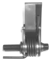
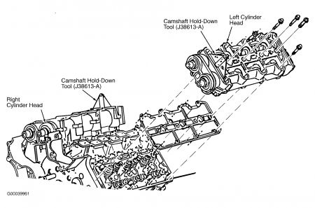
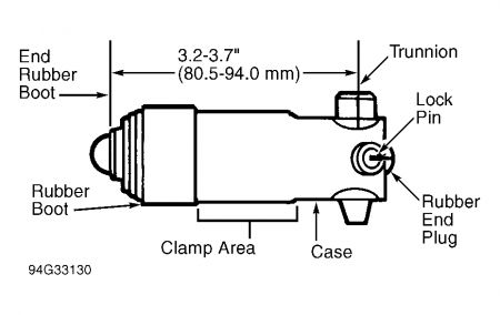
5. Fuel rail cover. 6. Relieve fuel pressure. 7. Fuel lines from fuel rail and remove fuel mounting bracket. 8. Heater hose and bracket from lower intake manifold. 9. PCV valve and vacuum line from throttle body. 10. Electrical connector from EGR. 11. EGR valve and reposition. 12. Electrical connections from canister purge solenoid and MAP sensor. 13. Vacuum lines from upper intake manifold tee. 14. Wiring loom bracket for rear spark plug wires. 15. Power brake vacuum hose and remove upper intake manifold. 16. Coolant recovery tank. 17. Serpentine belt. 18. Serpentine belt tensioner. 19. Power steering lines from pump and reposition for pump removal. Refer to section 3B. 20. Reposition PCM (1991-93 ONLY). 21. PCM mounting bracket (1991-93 ONLY). 22. PCM electrical connectors and reposition (1994-95 ONLY). 23. Spark plug wires from spark plugs. 24. Wiring harness cover at right strut tower. 25. Fuel line bracket. 26. Timing belt covers. 27. Breather hose from rear camshaft cover and crankcase vent from breather manifold. 28. Camshaft carrier covers. 29. Side plate bolts from actuator. 30. Rotate actuator assembly from the tensioner pulley socket and out of the mounting base. 31. Timing belt tensioner pulley. 32. Position actuator in vertical position in vise (rod tip down), clamp actuator body in vise lightly. See Fig. 1
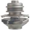
NOTE: Allow oil to drain to boot end for at least 5 minutes prior to refilling. The actuator assembly uses a tapered bushing between the actuator and mounting base. Do not lose or damage the bushing when removing the actuator assembly.
Fig. 1: Timing Belt Tensioner Actuator
33. Straighten out a standard paper clip (0.032 inch diameter, NO SERRATIONS) to minimum straight length of 47 mm (1.85 inches). Form a double loop in the remaining end of the paper clip. 34. Rubber end plug from the rear of the actuator assembly. The assembly is filled with oil and removal of the plug may allow oil to escape. ** DO NOT REMOVE VENT PLUG.**

SECTION 6A9 - REVISED CAMSHAFT TIMING PROCEDURE -1991 Pontiac Grand.
Page 3 of 5
35. Push the paper clip through the center of the vent plug and into the pilot hole. 36. Insert a small screwdriver into the screw slot inside the actuator, behind the rubber end plug. 37. Retract actuator plunger by rotating screw in a clockwise direction, until it is fully retracted. Push on paper clip and slowly rotate screw counterclockwise until paper clip engages. 38. Timing belt.
NOTE: Remove timing marks from camshaft and intermediate shaft sprockets.
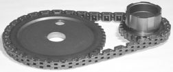
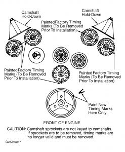
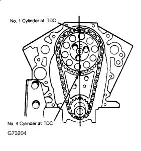
39. Rotate crankshaft so the #1 cylinder is at TDC (Top Dead Center). - Mark the timing indicator with white paint (or equivalent) on the crankshaft balancer and front cover.
Fig. 2: Crankshaft Reference Marks
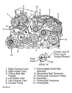
40. Position camshafts so the flat spots are "UP" for installation of J38613-A. 41. Install J38613-A on both camshaft carriers. 42. Camshaft sprockets. See Fig. 2.
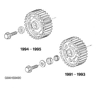
- 1991-93 REMOVE BOLTS, WASHERS, AND SPROCKETS USING J38614.
- 1994-95 REMOVE BOLTS, TAPER LOCK RINGS, AND SPROCKETS BY LIGHTLY TAPPING ON IT WITH A SOFT FACED HAMMER.
Fig. 3: Camshaft Timing Sprockets
INSTALL OR CONNECT
1. Camshaft sprockets. - 1991-93 Camshaft sprockets with washers and new locks finger tight. - 1994-95 Camshaft sprockets with taper lock rings finger tight. 2. Timing belt in a counterclockwise direction around the sprockets.
NOTE: Make sure timing belt teeth are fully engaged with all sprockets.
3. Timing belt tensioner pulley. Tighten: Tensioner pulley bolt to 50 N.M (37 Ft-Lbs). 4. If actuator oil has been lost, fill the actuator with SAE 5W30 Mobil 1 (or equivalent) synthetic engine oil through the end hole. Fill to bottom of plug hole only when actuator is fully retracted and pin is installed. 5. Rubber end plug to rear of the actuator assembly. - Push until flush and snapped into place. - Make sure the end plug has sealed against the case. 6. Actuator bushing into side plate. INSPECT: Bushings and appropriate holes to make sure they are clean. DO NOT LUBRICATE. 7. Timing belt actuator and actuator side plate. TIGHTEN: Side plate bolt to 27 N.M (20 Ft-Lbs).
NOTE: Rotate pulley assembly into belt a maximum of 15 N.M to allow engagement of the actuator shaft into the pulley arm socket.

SECTION 6A9 - REVISED CAMSHAFT TIMING PROCEDURE -1991 Pontiac Grand.
Page 4 of 5
8. Pull the lock pin and discard. Retorque pulley assembly 15 N.M counterclockwise to seat pulley into belt. TIGHTEN: Both right hand (rear bank) camshaft sprocket bolts to 130 N.M (96 Ft-Lbs). 9. Remove J38613-A from right hand (rear bank) camshaft carrier. 10. Rotate crankshaft 360 degrees clockwise while looking at front at engine and align crankshaft reference marks. INSPECT: Make sure both right hand (rear bank) camshaft flats are down. TIGHTEN: Both left hand (front bank) camshaft sprocket bolts to 130 N.M (96 Ft-Lbs). 11. Remove J38613-A from left hand (front bank) camshaft carrier. 12. Rotate crankshaft 720 degrees clockwise while looking at front of engine to seat timing belt and verify correct timing. INSPECT: Make sure both camshaft flatspots are up on one bank and down on the opposing bank. 13. Camshaft carrier covers and bolts. TIGHTEN: Bolts to 11 N.M (97 INCH Lbs). 14. Breather hose from rear camshaft cover and crankcase vent from breather manifold. 15. Timing belt covers and bolts. TIGHTEN: Bolts to 10 N.M (89 INCH Lbs). 16. Fuel line bracket and bolt. TIGHTEN: Bolt to 7 N.M (62 INCH Lbs). 17. Wiring harness cover at right strut tower. 18. Spark plug wires. 19. PCM electrical connectors. 20. Power steering lines to pump. 21. Serpentine belt. 22. Serpentine belt tensioner. TIGHTEN: Serpentine belt tensioner bolt to 45 N.M (33 Ft-Lbs). 23. Coolant recovery tank. 24. Upper intake manifold, bolts, and nuts. TIGHTEN: Bolts and nuts to 27 N.M (22 Ft-Lbs). 25. Power brake vacuum hose. 26. Wiring loom bracket for rear spark plug wires. 27. Vacuum lines to upper intake manifold tee. 28. Electrical connections to canister purge solenoid and MAP sensor. 29. EGR valve and bolts. TIGHTEN: Bolts to 25 N.M (18 Ft-Lbs). 30. Electrical connectors from EGR. 31. PCV valve and vacuum line to throttle body. 32. Heater hose and bracket to lower intake manifold. Refer to Section 6B. 33. Fuel mounting bracket and bolt. 34. Fuel lines to fuel rail. Refer to Section 6C. 35. Fuel rail cover. Refer to Section 6C. 36. Accelerator and cruise control cables to throttle body. 37. Air cleaner assembly. Refer to Section 6E3-C14. 38. Refill cooling system. Refer to Section 6B. 39. Refill power steering system. Refer to Section 3B. 40. Negative battery cable.

SECTION 6A9 - REVISED CAMSHAFT TIMING PROCEDURE -1991 Pontiac Grand.
Page 5 of 5
Labor Operation: J0800
Labor Time: 3.8 HOURS - 1991-93
3.1 HOURS - 1994-95
Was this
answer
helpful?
Yes
No
+2
Wednesday, October 7th, 2020 AT 11:47 AM (Merged)
Tiny
JAIME MENCHACA
  • MEMBER
  • 1 POST
  • 1991 PONTIAC GRAND PRIX
  • 3.4L
  • 6 CYL
  • AUTOMATIC
  • 60,000 MILES
Is there any way to be able to tell where exactly everything should be turned or aligned to if some/all of the pulleys have been moved?
Was this
answer
helpful?
Yes
No
Wednesday, October 7th, 2020 AT 11:47 AM (Merged)
Tiny
KEN L
  • MASTER CERTIFIED MECHANIC
  • 42,883 POSTS
Hello,

Yes you can realign the pulleys. Here is a guide to help you with that.

https://www.2carpros.com/diagrams/pontiac/grand-prix/1991

Please let us know if you need anything else to get the problem fixed.

Cheers, Ken
Was this
answer
helpful?
Yes
No
Wednesday, October 7th, 2020 AT 11:48 AM (Merged)
Tiny
TOMMYM3
  • MEMBER
  • 1 POST
  • 1991 PONTIAC GRAND PRIX
Engine Performance problem
1991 Pontiac Grand Prix 6 cyl Front Wheel Drive Automatic

how do you time the 3.1engine on a 1991 pontiac grand prix
Was this
answer
helpful?
Yes
No
Wednesday, October 7th, 2020 AT 11:48 AM (Merged)
Tiny
BLUELIGHTNIN6
  • MECHANIC
  • 16,542 POSTS
Check out the diagrams (Below). Please let us know what happens.


https://www.2carpros.com/forum/automotive_pictures/261618_Graphic_156.jpg

Was this
answer
helpful?
Yes
No
Wednesday, October 7th, 2020 AT 11:48 AM (Merged)

Please login or register to post a reply.

Sponsored links