TIMING CHAIN REMOVAL/INSTALLATION L3
Warning
Fuel vapor is hazardous. It can very easily ignite, causing serious Injury and damage. Always keep sparks and flames away from fuel.
Fuel line spills and leakage are dangerous. Fuel can ignite and cause serious injuries or death and damage. Fuel can also irritate skin and eyes. To prevent this, always complete the "Fuel Line Safety Procedure".
Disconnect the negative battery cable.
Remove the plug hole plate.
Remove the spark plugs.
Remove the tire (RH).
Remove the under cover.
Loosen the water pump pulley bolt and remove the drive belt.
Remove the Crankshaft Position (CKP) sensor.
Drain the engine oil.
Remove the P/S oil pump with the oil hose still connected and position the P/S oil pump so that it is out of the way.
Remove the front drive shaft (RH) from the joint shaft.
Remove in the order indicated in the table above.
Install in the reverse order of removal.
Start the engine and:
Inspect for the engine oil, engine coolant, transaxle oil and fuel leakage.
Verify the ignition timing, idle speed and idle mixture.
Perform a road test.
Crankshaft Pulley Lock Bolt Removal Note
Remove the cylinder block lower blind plug.
Install the SST.
Rotate the crankshaft clockwise until the crankshaft is in the No.1 cylinder TDC position (until the balance weight is contacting the SST)
Hold the crankshaft pulley using the SSTs.
Chain Tensioner Removal Note
Hold the chain tensioner ratchet lock mechanism away from the ratchet stem using a thin screwdriver.
Slowly compress the tensioner piston.
Hold the tensioner piston using a 1.5 mm (0.059 in) wire or paper clip.
No.3 Engine Mount Rubber and No.3 Engine Joint Bracket Removal Note
Suspend the engine using the SST.
Engine Front Cover Removal Note
Remove the oil seal using a screwdriver as shown.
Oil Pump Sprocket Removal Note
Hold the oil pump sprocket using the SST.
Oil Pump Sprocket Installation Note
Hold the oil pump sprocket using the SST.
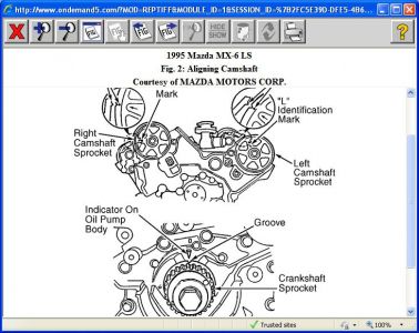
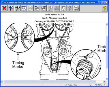
Timing Chain Installation Note
Install the SST to the camshaft as shown.
Install the timing chain.
Remove the retaining wire or paper clip from the auto tensioner to apply tension to the timing chain.
Engine Front Cover Installation Note
Apply silicone sealant to the engine front cover as shown.
Caution
Install the engine front cover within 10 minutes of applying the silicone sealant.
Silicone sealant is not needed in the area indicated by C as shown in the figure as it is a seal.
Thickness
A: 2.0 - 3.0 mm (0.079 - 0.118 inches)
B: 1.5 - 2.5 mm (0.059 - 0.098 inches)
Install the engine front cover bolts in the order as shown.
Front Oil Seal Installation Note
Apply clean engine oil to the oil seal.
Push the oil seal slightly in by hand.
Compress the oil seal using the SST and a hammer.
No.3 Engine Mount Rubber and No.3 Engine Joint Bracket Installation Note
Tighten the stud bolt of the No.3 engine mount bracket. Tightening torque 7.0 - 13 Nm (71.4 - 132.5 kgf-cm, 62.0 - 115.0 inch lbs.)
Hand-tighten the No.3 engine mount rubber and No.3 engine joint bracket.
Tighten the bolts and nuts
Crankshaft Pulley Lock Bolt Installation Note
Install the SST to the camshaft.
Install the M6 x 1.0 bolt in by hand.
Rotate the crankshaft clockwise until the crankshaft is in the No.1 cylinder TDC position (until the balance weight is contacting to the SST).
Hold the crankshaft pulley using the SST.
Tighten the crankshaft pulley lock bolt in the following two steps using the SST (49 D032 316).
1) Tighten to 96 - 104 Nm (9.8 - 10.6 kgf-cm, 70.9 - 76.7 ft. Lbs.)
2) Tighten 87°- 93°
Remove the M6 x 1.0 bolt.
Remove the SST from the camshaft.
Remove the SST from the cylinder block lower blind plug.
Rotate the crankshaft two times clockwise until the crankshaft is in the TDC position, reinstall the SSTs to the camshaft and cylinder block, and inspect the valve timing.
If not aligned, loosen the crankshaft pulley lock bolt and repeat from Step 1.
Install the cylinder block lower blind plug. Tightening torque 18 - 22 Nm (1.9 - 2.2 kgf-cm, 13.3 - 16.2 ft. Lbs.)
Cylinder Head Cover Installation Note
Apply silicone sealant to the mating faces as shown. Caution
Install the cylinder head cover within 10 minutes of applying the silicone sealant.
Thickness 4.0 - 6.0 mm (0.16 - 0.23 inches)
Install the cylinder head cover with a new gasket.
Friday, March 1st, 2019 AT 7:50 PM
(Merged)