I need to replacement the ignition lock key tumbler?

Tiny
CUTTINGTON5
  • MEMBER
  • 2003 ISUZU RODEO
  • 10,402 MILES
I would like to get instructions on how to change out the ignition key and lock.
Wednesday, January 2nd, 2013 AT 6:09 PM

13 Replies

Tiny
SATURNTECH9
  • MECHANIC
  • 30,870 POSTS
Here are the instructions on how to replace the ignition switch key lock. Check out the diagrams (Below). Please let us know if you need anything else to get the problem fixed.
Was this
answer
helpful?
Yes
No
+1
Wednesday, January 2nd, 2013 AT 6:15 PM
Tiny
TODD MULLINS
  • MEMBER
  • 1 POST
  • 2001 ISUZU RODEO
  • 6 CYL
  • 4WD
  • AUTOMATIC
  • 235 MILES
I bought this vehicle and the ignition was busted out. A friend got it started again by running a wire to the relay then to a toggle switch. What wires do I put together so I can have a toggle switch to turn on acceleration then a push button to start it? I do not know where to connect the wires.
Was this
answer
helpful?
Yes
No
Wednesday, May 26th, 2021 AT 1:23 PM (Merged)
Tiny
KEN L
  • MASTER CERTIFIED MECHANIC
  • 42,861 POSTS
Yes you can wire a switch and a push button to make the car work, here is a ignition switch wiring diagram so you can get the problem fixed.
Was this
answer
helpful?
Yes
No
-1
Wednesday, May 26th, 2021 AT 1:23 PM (Merged)
Tiny
STACEY EDSON
  • MEMBER
  • 1 POST
  • 2001 ISUZU RODEO
  • 178,000 MILES
I have tried turning the wheel, making sure it is in park, and all the other common things. It has done this a few times before, however after a few minutes of jiggling it has turned. This time however it is stuck. Any suggestions?
Was this
answer
helpful?
Yes
No
Wednesday, May 26th, 2021 AT 1:23 PM (Merged)
Tiny
KEN L
  • MASTER CERTIFIED MECHANIC
  • 42,861 POSTS
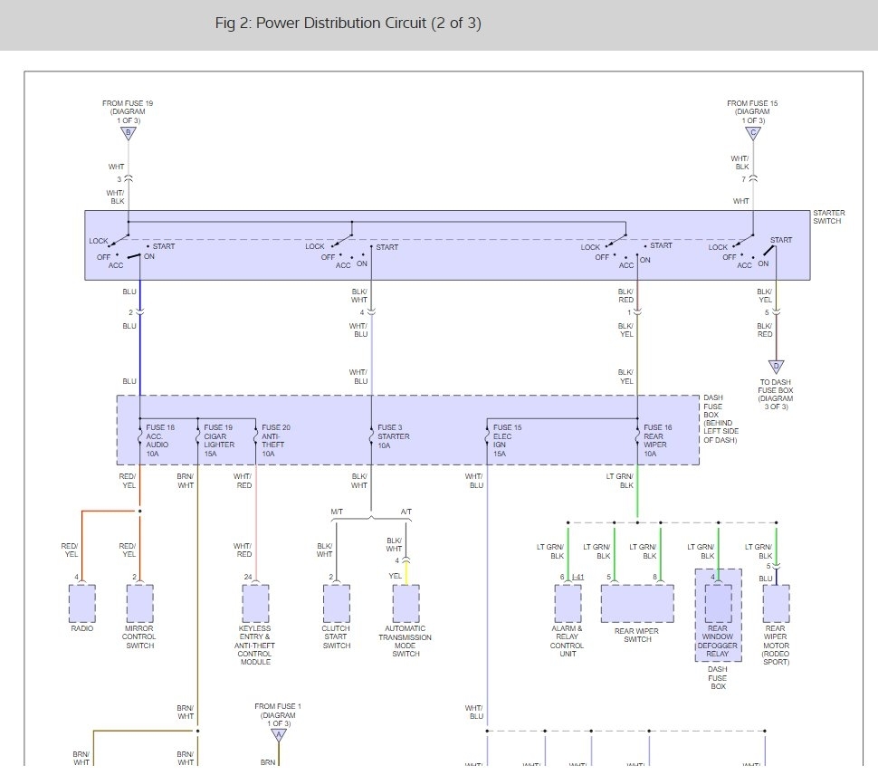
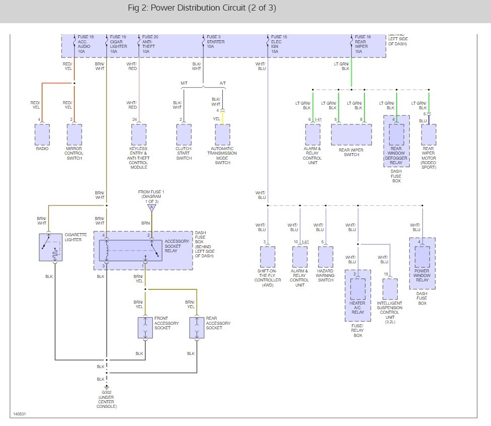
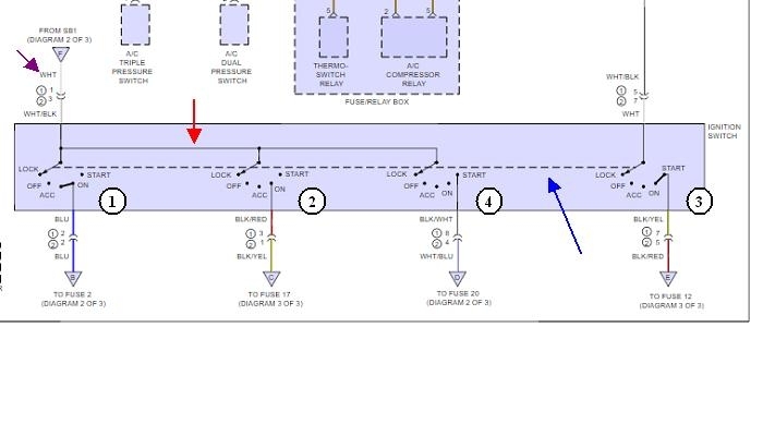
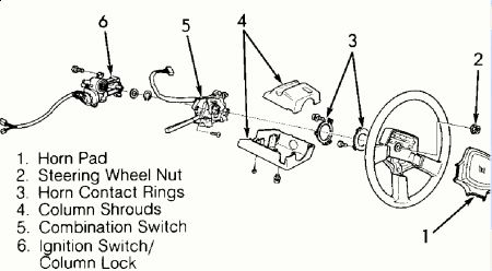
Yep, the ignition tumbler is worn out and needs to be replaced. Here are diagrams to help you get the job done you can get the part from Amazon or RockAuto:

Removal
1. Turn the steering wheel so that the vehicle's wheels are pointing straight ahead.
2. Turn the ignition switch to "LOCK".
3. Disconnect the battery "- " terminal cable, and wait at least 5 minutes.
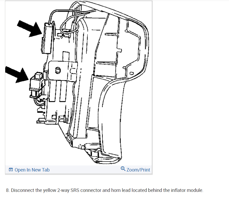
4. Disconnect the yellow 2-way SRS connector located under the steering column.

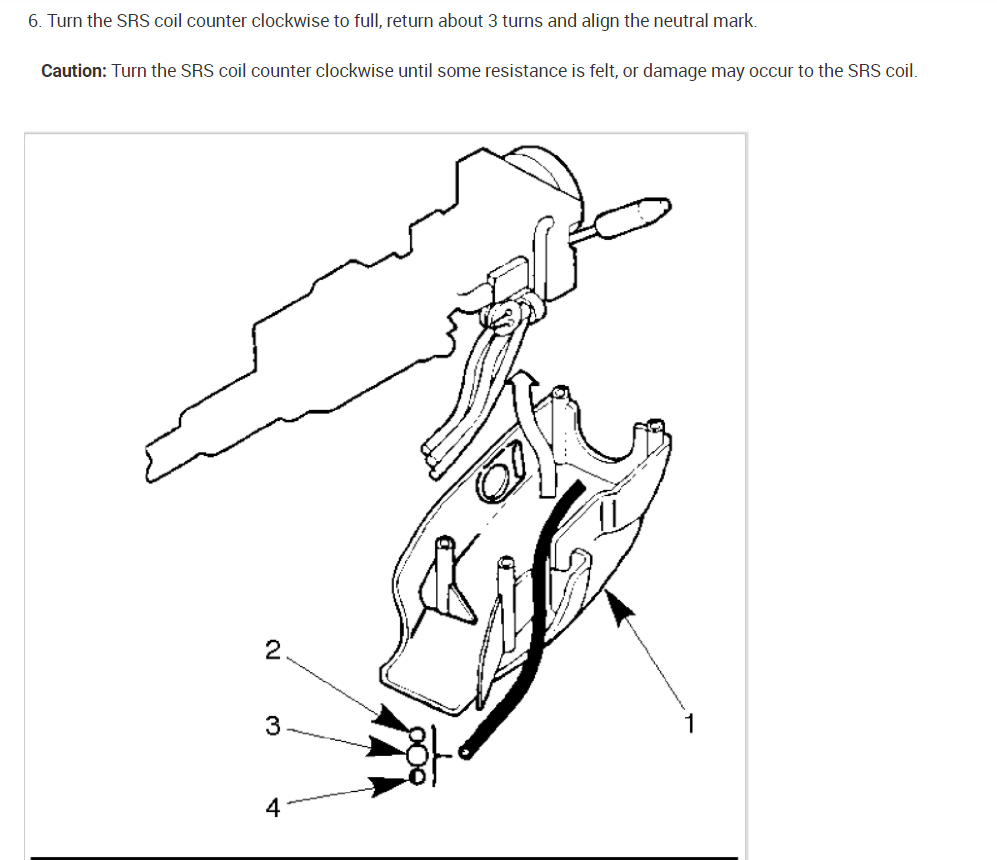
Caution: The wheels of the vehicle must be straight ahead and the steering column in the "LOCK" position before disconnecting the steering wheel. Failure to do so will cause the coil assembly to become uncentered which will cause damage to the coil assembly.

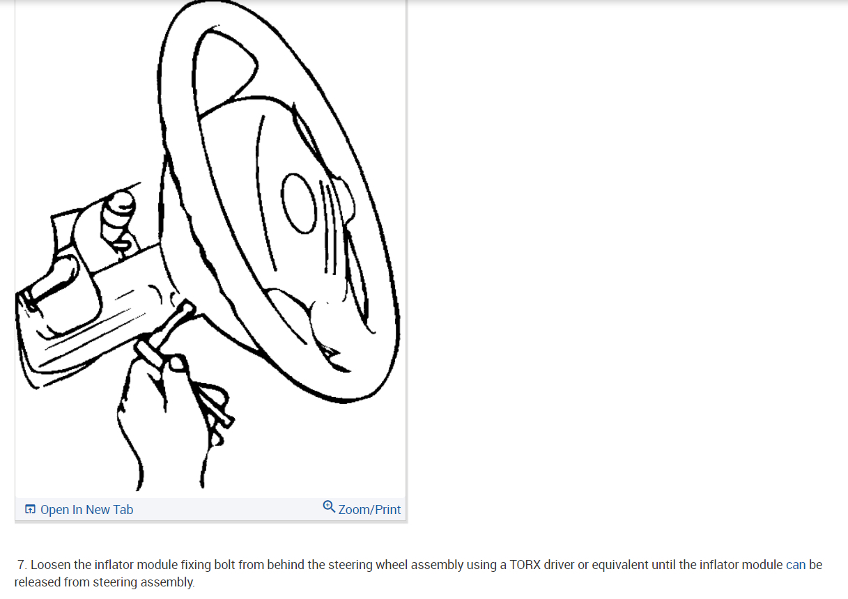
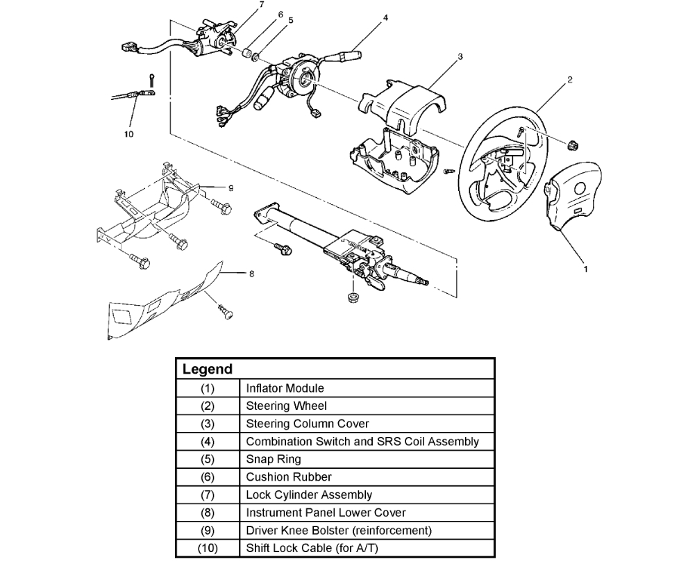
5. Remove the engine hood opening lever and steering lower cover.
6. Remove driver knee bolster (reinforcement).

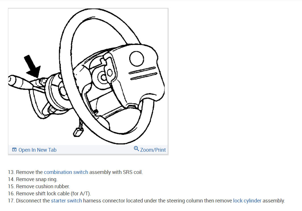
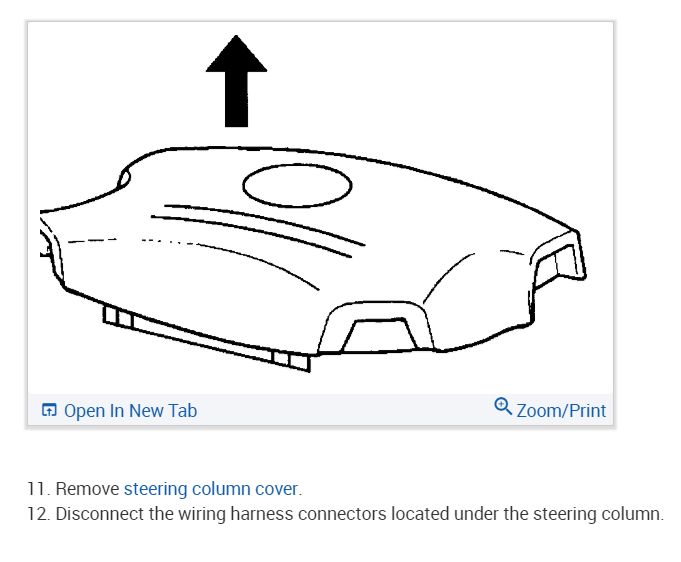
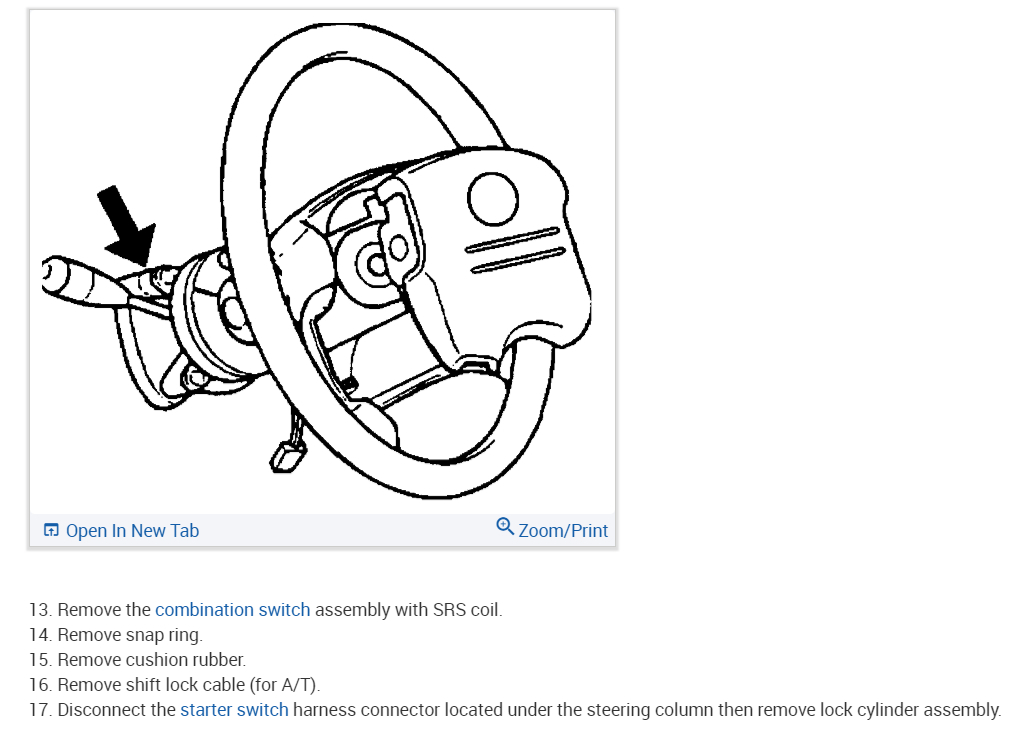
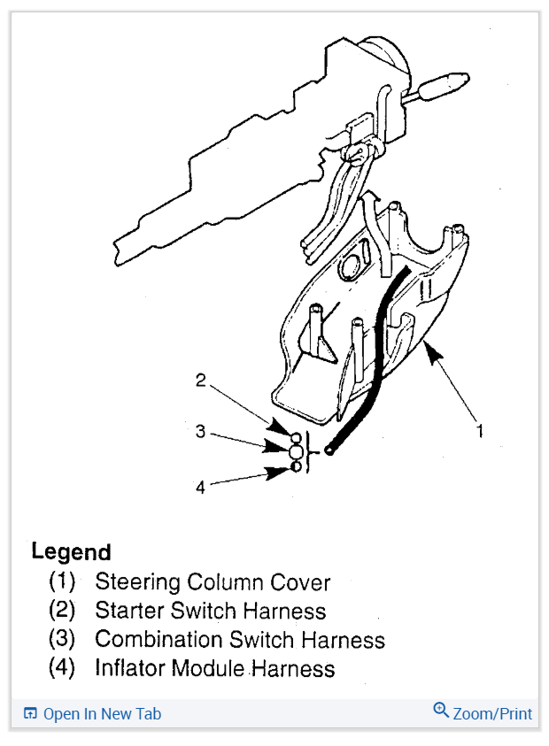
7. When installing the steering column cover, be sure to wire (through each harness) as illustrated so that the harnesses starter switch, combination switch and SRS coil may not catch wiring.
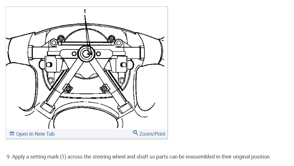
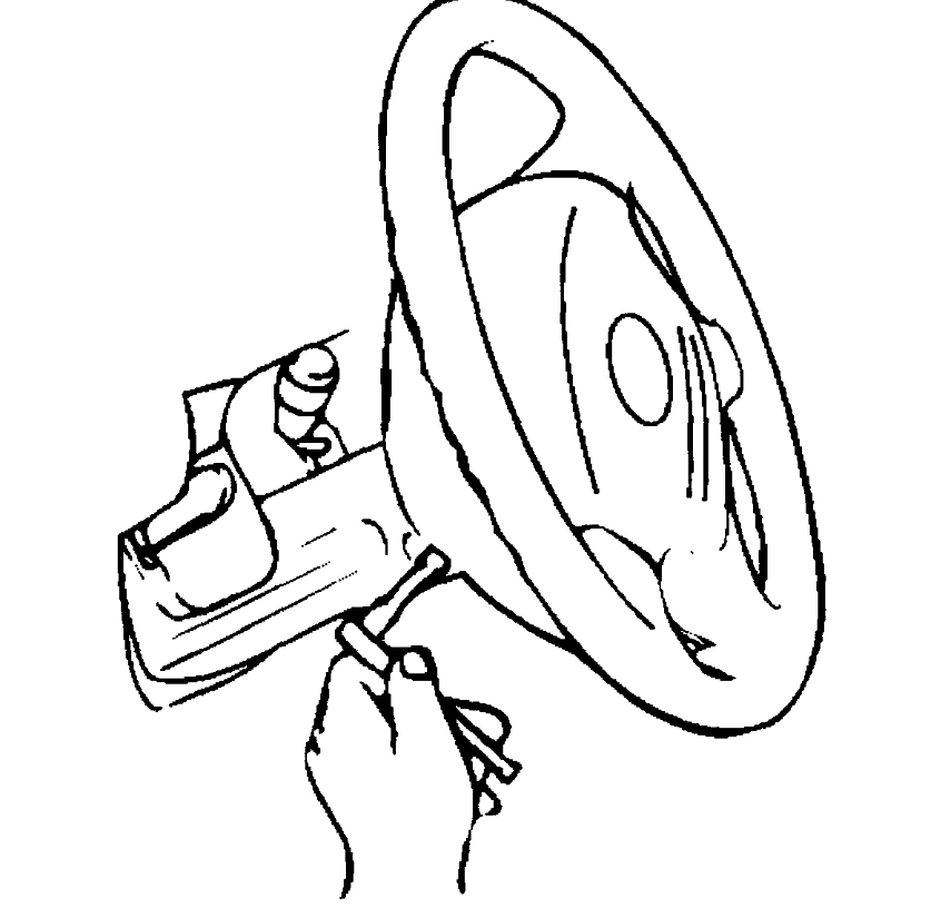
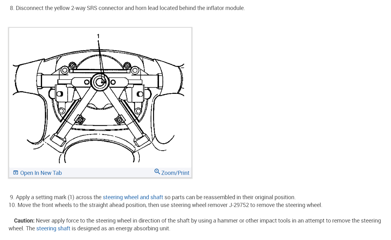
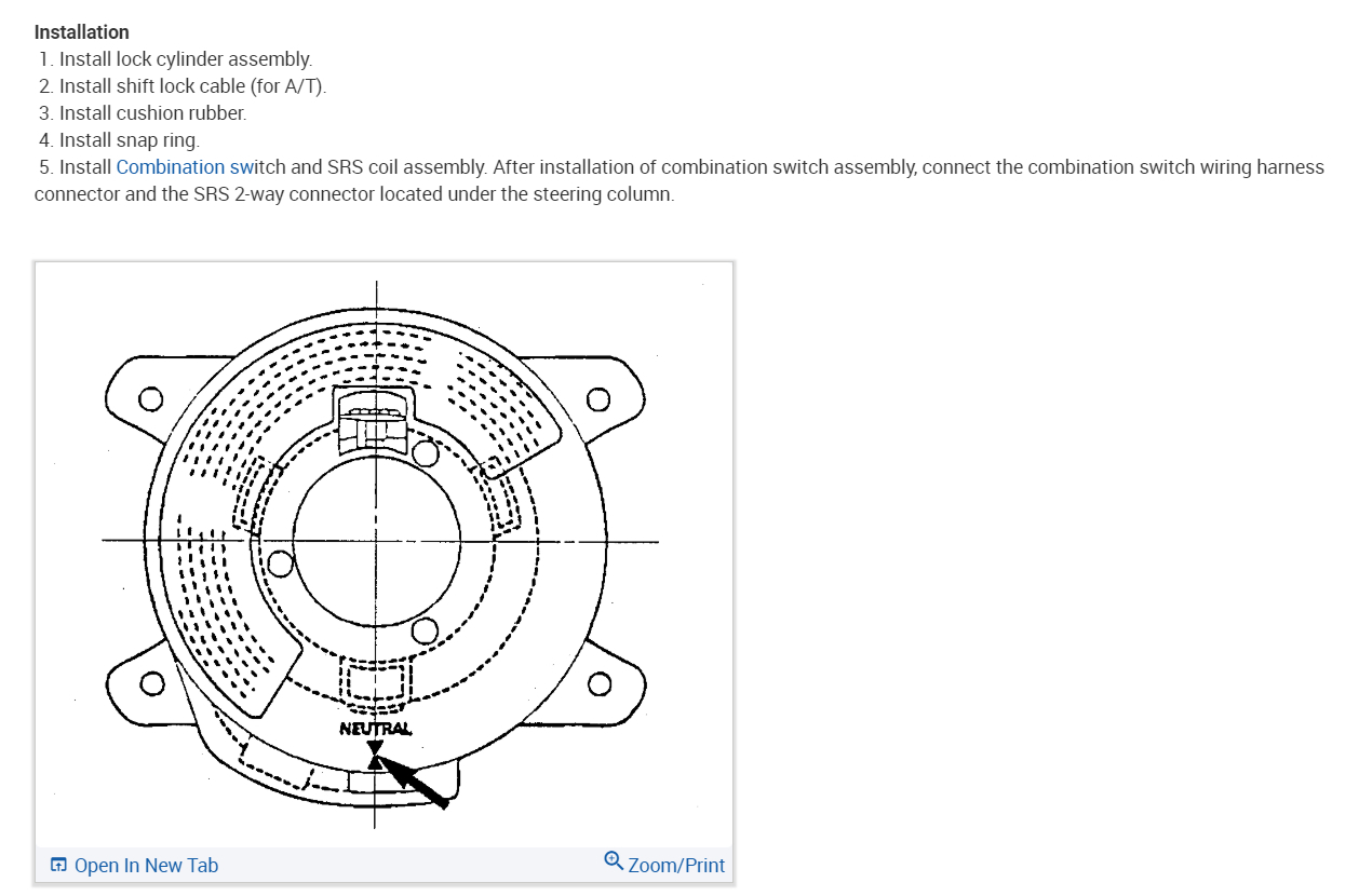
8. Install steering wheel by aligning the setting marks made during removal.

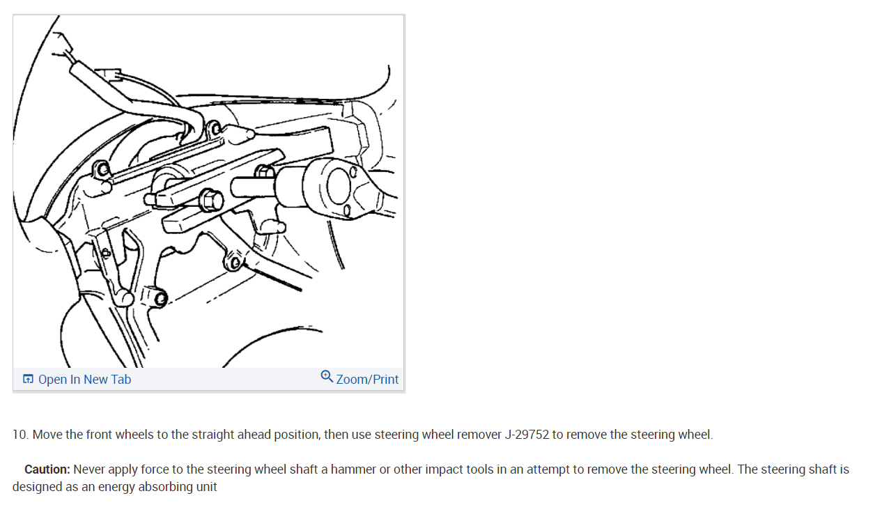
Caution: Never apply force to the steering wheel in direction of the shaft by using a hammer or other impact tools in an attempt to remove the steering wheel. The steering shaft is designed as an energy absorbing unit.

9. Tighten the steering wheel fixing nut to the specified torque.
Torque: 34 Nm (25 ft. Lbs.)
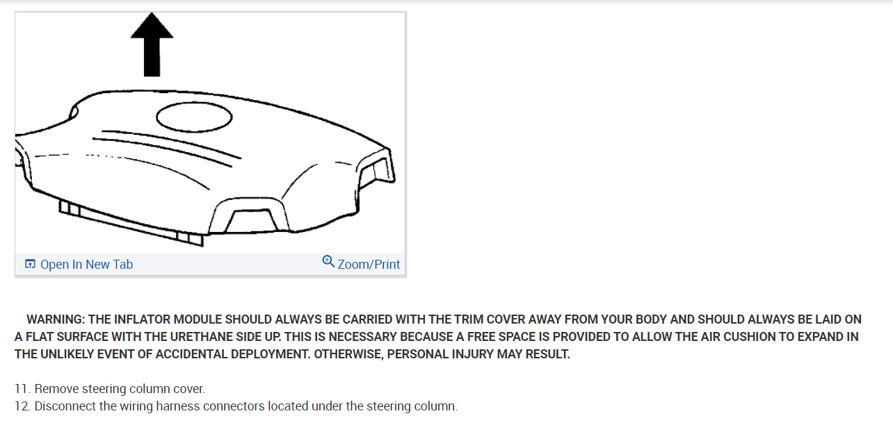
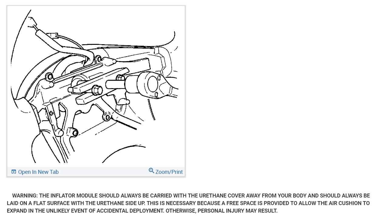
10. Support inflator module and carefully connect the SRS connector and horn lead, then install inflator module.

Note: Pass the lead wire through the tabs on the plastic cover (wire protector) of inflator to prevent lead wire from being pinched.

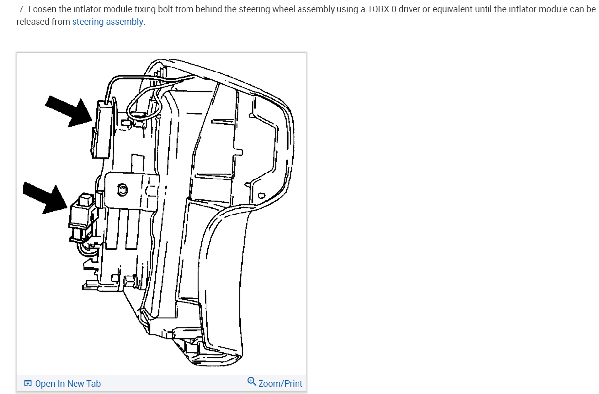
11. Tighten fixing bolts to specified torque.
Torque: 9 Nm (78 inch lbs.)
12. Install driver knee bolster (reinforcement).
13. Install instrument panel lower cover, then install the engine hood opening lever.
14. Connect the yellow 2-way SRS connector located under the steering column.
15. Connect the battery ground cable.

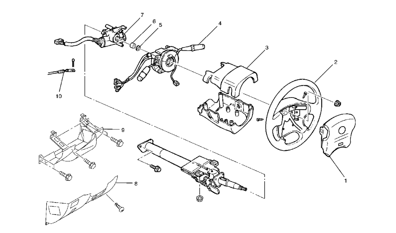
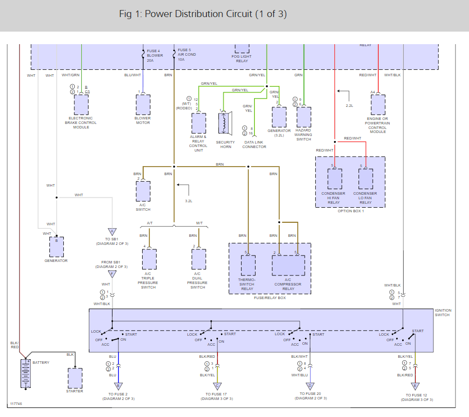
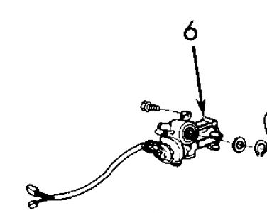
Check out the diagrams (below). Please let us know if you need anything else to get the problem fixed.

Cheers, Ken
Was this
answer
helpful?
Yes
No
Wednesday, May 26th, 2021 AT 1:23 PM (Merged)
Tiny
CARRIEPULIDO
  • MEMBER
  • 2 POSTS
  • 1999 ISUZU RODEO
  • 0.6L
  • 6 CYL
  • 18,000 MILES
The problem is the ignition switch has six wires, two battery, two ignition, one start and one accessories. Which ones would go to a toggle switch and which ones would go to a push button? Thank you.
Was this
answer
helpful?
Yes
No
Wednesday, May 26th, 2021 AT 1:23 PM (Merged)
Tiny
KEN L
  • MASTER CERTIFIED MECHANIC
  • 42,861 POSTS
Here is the ignition switch wiring so you can see how the switch is wired. It was under power distribution in FYI

Check out the diagrams (Below)Please let us know what happens.
Was this
answer
helpful?
Yes
No
+2
Wednesday, May 26th, 2021 AT 1:23 PM (Merged)
Tiny
CARADIODOC
  • MECHANIC
  • 33,737 POSTS
Thanks brother Ken.

CARRIEPULIDO, you'll need three toggle or rocker switches, and one push button switch if you want to do the switching the way the original switch does it. I can tell you which wires to connect if you can't figure it out from the diagram.
Was this
answer
helpful?
Yes
No
+1
Wednesday, May 26th, 2021 AT 1:24 PM (Merged)
Tiny
CARRIEPULIDO
  • MEMBER
  • 2 POSTS
Three? Ok I am going to need help which wires go to what? I will come back and give you the six wire colors and what they go to. Thank you I can't wait to see how this is done. Carrie
Was this
answer
helpful?
Yes
No
+1
Wednesday, May 26th, 2021 AT 1:24 PM (Merged)
Tiny
CARADIODOC
  • MECHANIC
  • 33,737 POSTS
This is going to take a while, so to get started, here's the ignition switch with some descriptions.

There's four switches built into the ignition switch assembly. The dashed line, (blue arrow) shows that all four of them turn together when you turn the key. Multiple switches are needed so the various circuits turn on and off at different times.

The purple arrows are pointing to two of the six wire color designations, in this case, two different 12-volt feed wires. The left one is white and the right one is white with a black tracer, (stripe).

The second drawing shows my representation of three rocker or toggle switches, and one push button switch. I'll repost that one once I figure out what each one controls. All of these switches are "single pole, single throw", (SPST), meaning they each have just one switch with a simple on or off position. More-complicated double pole and / or double throw switches can be used, but the extra terminals just won't be used. If you have to buy these switches, look for the SPST switches because they will cost less.
Was this
answer
helpful?
Yes
No
+1
Wednesday, May 26th, 2021 AT 1:24 PM (Merged)
Tiny
CARADIODOC
  • MECHANIC
  • 33,737 POSTS
One terminal each on switches 1, 2, and 4 are tied together, then those are all tied to the white wire. I showed them all as white wires.

The white / black wire goes to one terminal on switch 3.

The blue wire connects to the second terminal on switch 1.

The black / red wire connects to the second terminal of switch 2.

The black / yellow wire goes to the second terminal on switch 3.

The black / white wire goes to the second terminal on push button switch 4.

For the "Accessory" position, turn on switch 1.
For the "On" position, turn on switches 1, 2, and 3.
For the "Start" position, turn switches 1 and 2 off, leave switch 3 on, then press switch 4.

You can probably leave switches 1 and 2 on during cranking. Those are high-current circuits so they're normally turned off during cranking to save the battery's power for cranking.

Can't delete the first drawing. Use the second drawing.
Was this
answer
helpful?
Yes
No
+2
Wednesday, May 26th, 2021 AT 1:24 PM (Merged)
Tiny
AZANDFORD
  • MEMBER
  • 1 POST
  • 1992 ISUZU RODEO
  • 4 CYL
  • 4WD
  • MANUAL
  • 100,000 MILES
The cylinder would no longer accept my keys anymore. I needed it to go to the airport so I popped off the ignitin switch running to the cylinder and just used a screwdriver to get started and popped the steering wheel lock pin. I want to replace the cylinder but I cant get it out. I have tried everything. I have pulled pried and twisted it for like 2 hours but it only moved a little bit. I did not see anything on the outside holding it in place. I tried to tap it out from where the ignition switch meets the cylinder but still no luck. Am I overlooking something completely obvious or do I have the most stubborn cylinder in the world. Much appreciated, it looks like a stolen car every time I start it w/ a screwdriver. It isnt stolen by the way.
Was this
answer
helpful?
Yes
No
Wednesday, May 26th, 2021 AT 1:24 PM (Merged)
Tiny
MERLIN2021
  • MECHANIC
  • 17,250 POSTS
IGNITION SWITCH/C0LUMN LOCK ASSEMBLY Removal & Installation (Amigo, Pickup & Rodeo) 1. Disconnect battery negative cable. Remove horn pad and steering wheel. See STEERING WHEEL & HORN PAD . Remove upper and lower column shrouds and lower instrument panel. SeeFig. 7 . Disconnect both ignition switch and combination switch wiring connectors, located behind lower instrument panel. Remove tie-straps retaining harnesses to column. 2. Remove combination switch retaining bolts, and slide switch from shaft. SeeFig. 7 . Remove snap ring and bushing from in front of ignition switch. Turn ignition switch to ON position to unlock column. 3. Remove ignition switch and column lock assembly retaining bolts from rear of switch assembly. To access switch assembly retaining bolts, it may be necessary to remove upper column bracket bolts from instrument panel in order to lower steering column. Slide switch assembly from shaft. 4. To install, reverse removal procedure. Ensure proper operation of steering lock and ignition switch mechanism before completing reassembly of column components. Tighten all bolts to specification. See TORQUE SPECIFICATIONS NOTE: Ignition lock set removal procedures are not available form manufacturer.


https://www.2carpros.com/forum/automotive_pictures/62217_rodeo_2.jpg


https://www.2carpros.com/forum/automotive_pictures/62217_rodeoa_2.jpg

Was this
answer
helpful?
Yes
No
+3
Wednesday, May 26th, 2021 AT 1:24 PM (Merged)

Please login or register to post a reply.

Sponsored links