We could do the last 2 tests, to see what voltage/ohms your getting? From PCM to CKP
1) Check CKP+ Circuit To PCM
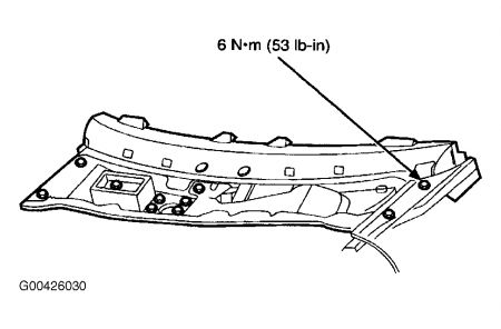
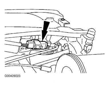
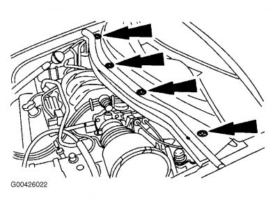
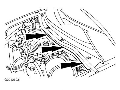
Turn ignition off. Disconnect PCM 104-pin connector. Inspect connector for loose, damaged or corroded terminals. Repair as necessary. Turn ignition on. Measure voltage between PCM connector pin No. 21 (CKP+) and CKP+ terminal at CKP sensor wiring harness connector. See Fig. 145-Fig. 148. Also measure resistance between PCM connector pin No. 22 (CKP-) and CKP- terminal at CKP sensor wiring harness connector. If both resistance readings are 5 ohms or less, go to next step. If any resistance reading is more than 5 ohms, repair open circuit.
2) Check For CKP+ Voltage Fault
Reconnect PCM connector. Turn ignition on. Measure voltage between CKP+ terminal at CKP sensor wiring harness connector and negative battery terminal. If voltage is more than one volt, but less than 2 volts, go to next step. If voltage is not as specified, go to step 19).
3) Check For CKP- Voltage Fault
Ensure ignition is on. Measure voltage between CKP- terminal at CKP sensor wiring harness connector and negative battery terminal. If voltage is 1-2 volts, go to step 10). If voltage is not 1-2 volts, go to next step.
4) Determine Fault
If voltage reading in step 3) is less than one volt, go to next step. If voltage reading in step 3) is not less than one volt, go to step 6).
5) Check CKP- Circuit For Short To Ground
Turn ignition off. Disconnect PCM connector. Measure resistance between PCM connector pin No. 22 and negative battery terminal. If resistance is more than 10,000 ohms, replace PCM. If resistance is less than 10,000 ohms, repair CKP- circuit short to ground.
6) Check CKP- Sensor For Short To Power
Disconnect PCM connector. Turn ignition on. Measure voltage between PCM connector pin No. 22 and negative battery terminal. If voltage is.5 volt or more, repair CKP- circuit short to power. If resistance is less than.5 volt, replace PCM.
NOTE:A break in step numbering sequence occurs at this point. Procedure skips from step 6) to step 10). No test procedures have been omitted.
10) Check CKP Sensor Voltage At PCM
Turn ignition off. Reconnect CKP sensor connector. Disconnect PCM connector. While cranking engine, measure voltage between PCM connector pins No. 21 and 22. If A/C voltage stabilized at more than.4 volt, CKP circuit is okay. Go to step 17). If voltage is.4 volt or less, go to next step.
NOTE:A break in step numbering sequence occurs at this point. Procedure skips from step 10) to step 12). No test procedures have been omitted.
12) Check CKP Circuit Resistance
Turn ignition off. Measure resistance between PCM connector pins No. 21 and 22. If resistance is 300-800 ohms, go to step 16). If resistance is not 300-800 ohms, go to next step.
13) Determine Fault
If resistance is less than 300 ohms in step 12), go to next step. If resistance is not less than 300 ohms in step 12), replace CKP sensor.
14) Check For Open Circuit
Disconnect CKP sensor connector. Measure resistance between CKP sensor wiring harness connector terminals. If resistance is less than 5 ohms, repair CKP+ to CKP- short circuit. If resistance is 5 ohms or more, replace CKP sensor.
NOTE:A break in step numbering sequence occurs at this point. Procedure skips from step 14) to step 16). No test procedures have been omitted.
16) Check CKP Sensor & Trigger Wheel
Check CKP sensor and trigger wheel for damage. Repair as necessary. If CKP sensor and trigger wheel are okay, replace CKP sensor.
17) Check For PCM Fault
Turn ignition off. Disconnect CKP sensor connector. Reconnect PCM connector. Measure resistance between CKP sensor wiring harness connector terminals. If resistance is 16,000-24,000 ohms, go to next step. If resistance is not 16,000-24,000 ohms, replace PCM.
18) Check For Short Circuit
Ensure CKP sensor is disconnected. Disconnect PCM connector. Measure resistance between PCM connector pins No. 21 and 22. If resistance is more than 1000 ohms, replace CKP sensor. If resistance is 1000 ohms or less, repair short circuit.
19) Determine Fault
If voltage reading in step 2) is less than one volt, go to next step. If voltage reading in step 2) is not less than one volt, go to step 21).
20) Check CKP+ Circuit For Short To Ground
Turn ignition off. Disconnect PCM connector. Measure resistance between PCM connector pin 21 and negative battery terminal. If resistance is more than 10,000 ohms, replace PCM. If resistance is less than 10,000 ohms, repair CKP+ circuit short to ground.
21) Check CKP+ Sensor For Short To Power
Turn ignition off. Disconnect PCM connector. Turn ignition on. Measure voltage between PCM connector pin No. 21 and negative battery terminal. If voltage is.5 volt or more, repair CKP+ circuit short to power. If voltage is less than.5 volt, replace PCM.
Monday, December 22nd, 2008 AT 5:31 PM