Loss of power when driving

Tiny
BARBARA MCALLISTER
  • MEMBER
  • 1988 FORD F-250
  • V8
  • 4WD
  • AUTOMATIC
My Ford F250 won't go over 25 mph. I have so far changed the vacuum modulator and that doesn't seem to help. What next?
Barry Jackson
Sunday, March 27th, 2011 AT 11:38 PM

36 Replies

Tiny
CJ MEDEVAC
  • MECHANIC
  • 11,004 POSTS
Is it really running rough/ smoking/ etc. While trying to accelerate? Investigate a Stopped up Catalytic Converter.--The Medic
Was this
answer
helpful?
Yes
No
-3
Sunday, March 27th, 2011 AT 11:46 PM
Tiny
BARBARA MCALLISTER
  • MEMBER
  • 4 POSTS
I don't know if this matters, but, it runs at 4,000 rpms when the engine is cold. Once it gets warmed up, it drops to 2,500 rpms. Do you still think catalytic converter?
Thank you for your time, Barry Jackson
Was this
answer
helpful?
Yes
No
Monday, March 28th, 2011 AT 12:05 AM
Tiny
CJ MEDEVAC
  • MECHANIC
  • 11,004 POSTS
Any other observations? Does your Check Engine light work at start-up. Is it/ Has it been on constantly?--The Medic
Was this
answer
helpful?
Yes
No
+2
Monday, March 28th, 2011 AT 1:59 AM
Tiny
BARBARA MCALLISTER
  • MEMBER
  • 4 POSTS
No, just loses power once it gets warmed up. Anything else besides the catalytic converter? Thanks Again, Barry Jackson
Was this
answer
helpful?
Yes
No
Monday, March 28th, 2011 AT 2:00 AM
Tiny
CJ MEDEVAC
  • MECHANIC
  • 11,004 POSTS
Attempting a solution for your problem. Trying to get you one soon, as to get you ridin' again. I did leave a message for another Expert to assist, If I cannot come up with a solution soon.---The Medic
Was this
answer
helpful?
Yes
No
-1
Monday, March 28th, 2011 AT 2:15 AM
Tiny
BARBARA MCALLISTER
  • MEMBER
  • 4 POSTS
Thank you so much! I appreciate all your help. Barry Jackson
Was this
answer
helpful?
Yes
No
-2
Monday, March 28th, 2011 AT 2:38 AM
Tiny
RASMATAZ
  • MECHANIC
  • 75,992 POSTS
For your idle problem

NOTE: A change in idle speed occurred because of a problem elsewhere. Enter this procedure after eliminating the possible causes listed below:

Contamination within the throttle bore and/or idle speed control device.
Throttle sticking or binding.
Engine not reaching operating temperature.
Vacuum leaks (air intake, vacuum hoses, vacuum reservoirs, power brake booster, etc.)
VERIFY:

Transmission is in PARK (A/T) or NEUTRAL (M/T).
Parking brake is APPLIED (automatic brake release is DISCONNECTED where applicable).
Wheels blocked.
Cooling system is filled to proper level.
Engine is at operating temperature.
All accessories (heater, radio, lights, etc.) OFF.
Throttle lever is resting ON the throttle plate stop screw.
Ignition timing is set to specification.
Perform EEC-IV diagnostics and resolve any vehicle malfunctions that are indicated by service codes. (Ignore this step if sent here from an EEC-IV Pinpoint Test step).
Engine OFF, disconnect the negative (-) terminal of the battery for 5 minutes minimum, then reconnect it. NOTE: Memory to radio, phone, and other programmable accessories may be erased when the battery is disconnected.
Idle Speed Setting

PROCEDURES

With engine OFF install specified feeler gauge between throttle plate stop screw and throttle lever. Automatic transmission.030 inches, manual transmission.030 inches.
Unplug SPOUT line and verify that ignition timing is 10°+/- 2°BTDC.
Disconnect idle speed control-air bypass solenoid.
With transmission in NEUTRAL (M/T) or PARK (A/T):
Allow engine to idle for 2 minutes.

Check/adjust idle rpm: Turn the throttle plate stop screw to 780 +25 rpm automatic transmission, 730 +25 rpm manual transmission.
NOTE: If you must turn the throttle stop screw IN, turn engine OFF, make estimated adjustment. START engine and repeat Steps 4, 5, and 6 before continuing.

Remove feeler gauge from throttle plate stop screw and throttle lever pad.
Reconnect SPOUT line.
Turn engine off and reconnect idle speed control-air bypass solenoid, verify the throttle is not stuck in the bore and linkage not preventing throttle from closing.
START engine and stabilize for 2 minutes then goose engine and let it return to idle, lightly depress and release the accelerator. Let engine idle, if problem exists, see Diagnosis by Symptom (Diagnostic Routines.)
NOTE: A condition may occur where the engine rpm will oscillate. This can be caused by the throttle plates being open enough to allow purge flow. To verify this condition, disconnect the carbon canister purge line and plug it. If purge is present, the throttle plates must be closed until the purge flow induced idle oscillations stop.

On Automatic Overdrive Transmission (AOD) applications check TV pressure adjustment, See Automatic Transmissions

Won't accelerate over 25mph-check and test the Airflow meter/sensor and throttle position sensor also check he fuel pressure -

**** What vacuum modulator did you replace -is for the tranny? Could very well be the transmission slipping
Was this
answer
helpful?
Yes
No
+1
Monday, March 28th, 2011 AT 4:10 AM
Tiny
SAVANAKAYE
  • MEMBER
  • 1 POST
  • 1988 FORD F-250
  • 7.5L
  • V8
  • 2WD
  • AUTOMATIC
I have a 1988 f250 460 7.5l. My truck start to have problems on the highway trying to get up to speed it would all of a sudden make a bunch of noise some of it sounding like a plastic bag blowing in the wind then engine would calm down and be good then back to noise trying to accelerate. Pulled over looked couldn't tell got back on the highway and it was just all noise and not wanting to accelerate. Just slowly moved down the highway at about 20 mph and then it started bogging down then died while the throttled was still pushed and would not start back up just cranking and trying. After about 30 mins it started but only while holding gas. It smelled very bad of gas and was very loud. Got it home and now it will idle decently but when you try to accelerate to about 2000 rpms it bogs down and sometimes dies. Also when you leave it idle it will shake like crazy. It also will sometimes die once it warms up. We have replaced the distriptor cap and rotor. The coil. And tested the ignition module. We are completely stuck. Please help
Was this
answer
helpful?
Yes
No
Tuesday, March 24th, 2020 AT 2:55 PM (Merged)
Tiny
HMAC300
  • MECHANIC
  • 48,601 POSTS
Check fuel pressure with a gauge auto parts rent it. Also check vacuum at intake if 15" or below at idle then suspect clogged exhaust. Fuel pressure should be 30-45 psi with key ononly
Was this
answer
helpful?
Yes
No
-2
Tuesday, March 24th, 2020 AT 2:55 PM (Merged)
Tiny
CAPTANRON
  • MEMBER
  • 16 POSTS
  • 1986 FORD F-250
1986 Ford F250 V8 Two Wheel Drive Automatic

I switched from mechanical fuel pump to electric Airtex E8012S, 5-9 psi, 30gph, new fuel filter, connected to 10amp fuse. I spliced into the 10amp fuse wire for the "aux fuel solenoid". Engine starts and idles fine. When I put the truck in gear and take off it spits sputters and gags and its a no go. It will idle in gear just fine.
Was this
answer
helpful?
Yes
No
-1
Tuesday, March 24th, 2020 AT 2:55 PM (Merged)
Tiny
CAPTANRON
  • MEMBER
  • 16 POSTS
Update: I called Airtex. The electric fuel pump manufacturer and discussed the problem. Turns out that the above fuel pump does not put out enough volume for a 460ci motor. Airtex suggested a E84070 pump. So went to O'Reilly's and got an Airtex #E84070 electric fuel pump. I will be installing it today.
Wish me luck!
Was this
answer
helpful?
Yes
No
-1
Tuesday, March 24th, 2020 AT 2:55 PM (Merged)
Tiny
MERLIN2021
  • MECHANIC
  • 17,250 POSTS
Good luck!
Was this
answer
helpful?
Yes
No
-1
Tuesday, March 24th, 2020 AT 2:55 PM (Merged)
Tiny
CAPTANRON
  • MEMBER
  • 16 POSTS
I installed the recommended pump from Airtex. Idled like crap. I re-adjusted the float level and tinkered with idle screw. Now it idles at least. Fuel pressure at the carb is almost 5psi. No leaks. Still no acceleration.
Bogs out when you rev the engine like its starving for fuel.
Help me out here guys, cuz i'm lost for causes and running out of money and patience. I have faith in you guys.
Was this
answer
helpful?
Yes
No
-1
Tuesday, March 24th, 2020 AT 2:55 PM (Merged)
Tiny
MERLIN2021
  • MECHANIC
  • 17,250 POSTS
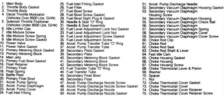
How did it run with the mechanical pump? If not good, your carb may need a new accelerator pump. This gives a shot of fuel for take off. Which carb is on it and I will see if I can locate a diagram.
Here are the specs and testing info for the fuel pump. Mechanical, you electric should be set to deliver this pressure.
FUEL PUMP
NOTE: 5.0L MPFI models use electric fuel pumps and 5.8L 4-Bbl. Models use
mechanical fuel pumps. On 7.5L 4-Bbl. Models, the Hot Fuel Handling
application uses in-tank mounted electric fuel pumps. All other
applications use mechanical fuel pumps.
Mechanical Fuel Pump (Volume Test)
On 5.8L and 7.5L 4-Bbl. Models, remove air cleaner. Slowly disconnect fuel line at filter. Using
a suitable container (one pint minimum), place at end of disconnected fuel line. With high
tension wire disconnected from coil, crank engine 10 seconds. If fuel flow is within
specification, proceed to pressure test. If not, proceed to next step.
1.
If fuel flow is low, repeat test using remote vented can of gasoline. Remove fuel pump inlet
hose. Connect a length of fuel line hose to fuel pump inlet and insert other end into remote can
of gasoline. If fuel flow is within specification, problem is plugged intake fuel filter or a kinked,
leaking or plugged fuel line or hose.
2.
Mechanical Fuel Pump (Pressure Test)
Remove air cleaner. Connect suitable pressure tester to end of fuel line. Start engine and let run for at
least thirty seconds. Read pressure and if not within specification, replace fuel pump. Reinstall air
cleaner.
Electric Fuel Pump
On 5.0L MPFI models, disconnect fuel return line at fuel rail. Connect hose to container. Connect
pressure gauge at diagnostic valve on fuel rail. Disconnect wiring connector at fuel tank and apply 12
volts to pump with jumper wire.
On 7.5L 4-Bbl. Models, disconnect fuel line just before the vapor separator unit. Connect a hose from
fuel line to a suitable container. If fuel flow is not within specification, electrically check fuel pump.
If still not within specification, replace pump-sender assembly.
FUEL PUMP SPECIFICATIONS
Application Specification
Electric Fuel Pumps
5.0L MPFI
Pressure (1) 39 psi (2.7 kg/cm2 )
Volume (1) 1 pint (.5L) in 30 seconds
7.5L 4-Bbl.
Pressure (1) 4.3 psi (.30 kg/cm2 )
Volume (1) 1 pint (.5L) in 20 seconds
Mechanical Fuel Pumps
Pressure 6.0-8.0 psi (.42-.56 kg/cm2 )
TUNE-UP - V8 -1986 Ford Pickup F250 Page 1 of 2
4/28/2010
Application Specification
Volume 1 pint (.5L) in 20 seconds
(1) Delivery capability averages.

TUNE-UP - V8 -1986 Ford Pickup F250 Page 2 of 2
4/28/2010
Was this
answer
helpful?
Yes
No
+1
Tuesday, March 24th, 2020 AT 2:55 PM (Merged)
Tiny
CAPTANRON
  • MEMBER
  • 16 POSTS
A big thank you Merlin for responding!

I have at normal idel 4.5 - 5 psi. At the carb. Starting cold 9 psi. At the carb. Fuel pump puts aout 72 gph. Working fine no leaks.

I discovered yesterday that if I manually close the choke plate almost closed and push the throttle open, it will run like a lion with turpintine on it's rear!

So i'm kinda leaning towards a bad fuel accelerator pump?

What do you think?
Was this
answer
helpful?
Yes
No
-1
Tuesday, March 24th, 2020 AT 2:55 PM (Merged)
Tiny
MERLIN2021
  • MECHANIC
  • 17,250 POSTS
That was my first thought, but it might also need a mixture adjustment, fully warm motor should have a fully open choke. How old is the choke thermostat?
Was this
answer
helpful?
Yes
No
-1
Tuesday, March 24th, 2020 AT 2:55 PM (Merged)
Tiny
CAPTANRON
  • MEMBER
  • 16 POSTS
I dont know about a choke "thermostat". The choke is electric. I just dont understand why I have to manually hold the choke plate at top of carb almost closed in order to get the engine to run at high speed. Pumping the throttle dosent keep it running unless I almost close the choke plate. Carb is getting enough fuel. Fuel pump puts out 72gph.
Acclelrator pump works. It's just getting enough fuel to keep running. I'm thinking there is an adjustment behind the electric choke. Like a little plastic thing with a tensioning spring. Wish I had a picture. Should be an adjustment for it.
Was this
answer
helpful?
Yes
No
-1
Tuesday, March 24th, 2020 AT 2:55 PM (Merged)
Tiny
IRONCOWBOY77
  • MEMBER
  • 2 POSTS
  • 1987 FORD F-250
  • V8
  • 4WD
  • AUTOMATIC
  • 19,700 MILES
My 87 F250 4X4 W/460 &C6 Trans Has a problem That is either a clogged fuel filter or in the ignition. Maybe in the brain box or distributor ect. It loses power on hills and pulling a trailer. Does MSG or other? Make a stock replacement for the fords brain box located on the drivers side wheel well. And where are the fuel filters located on this truck? Frame rail? & Carb inlet line? And between fuel pump & carb? Are there 3? How can I get this rig to run smooth and strong? Where do I start? Thanks Gail Ralls.206 818-0729 any time
Was this
answer
helpful?
Yes
No
-1
Tuesday, March 24th, 2020 AT 2:55 PM (Merged)
Tiny
JACOBANDNICKOLAS
  • MECHANIC
  • 108,128 POSTS
Yes an aftermarket brain is available for this truck. Also, the fuel filter should be along the frame rail. Also, there is only one fuel filter.

Based on your discription, it sounds like the catylatic converter may be plugging. Have you checked it?
Was this
answer
helpful?
Yes
No
-1
Tuesday, March 24th, 2020 AT 2:55 PM (Merged)
Tiny
MERLIN2021
  • MECHANIC
  • 17,250 POSTS
Any black smoke from the exhaust? Could be a vacuum leak or mixture adjustment. Is the carb a carter? holley?
Post a photo if you can. Also check the mounting gasket and hold down nuts, if the base gasket is cracked or loose, you will NEVER get it adjusted right... Snug the nuts down evenly, but not excessively. Here's a few simple things to check, Float is important and can be adjusted on Holley carbs without taking it off or disassembling it...
FLOAT LEVEL - WET 1. Start engine until it reaches normal operating temperature. Place vehicle on a flat surface. Remove air cleaner, if installed. Run engine at 1000 RPM for 30 seconds to stabilize fuel in carburetor. 2. Stop engine and remove sight plug from primary side fuel bowl. Check fuel level. Fuel level should be at bottom of sight plug hole. If fuel spills when plug is removed, lower fuel level by turning adjustment nut clockwise. 3. If fuel level is below sight plug hole, raise fuel level by turning adjustment nut counterclockwise. Turning adjustment nut 5/32" (4 mm) will change fuel level about 1/32" (.79 mm). 4. Tighten lock screw and install sight plug. Start and run engine at 1000 RPM for 30 seconds. Stop engine, remove sight plug and check fuel level. If necessary, adjust fuel level. 5. If fuel level is at bottom of sight plug, install sight plug using a new plug gasket. Repeat procedure for secondary fuel bowl. Secondary throttle MUST be used to stabilize fuel level in secondary fuel bowl. ACCELERATOR PUMP LEVER 1. Place throttle valves in wide open position. Using a feeler gauge, measure clearance between lever adjustment screw head and pump arm with pump arm manually depressed. See Fig. 3 . 2. To adjust, loosen adjustment screw lock nut. Turn adjustment screw in to increase clearance, and out to decrease clearance. Each 1/2 turn of adjustment screw equals .015" (.38 mm). Tighten lock nut. Fig. 3: Accelerator Pump Lever Adjustment
NOTE: Each 1/2 turn of adjustment screw equals .015" (.38 mm). ACCELERATOR PUMP STROKE Accelerator pump stroke has been preset at factory. Setting should not be changed. If original setting has been changed, adjust as follows: Check that plastic accelerator pump cam is aligned with correct hole (top or bottom) in throttle lever. Plastic accelerator pump cam is located behind throttle lever. If not aligned with correct hole, remove screw. Reposition in correct hole. Install and tighten screw. SECONDARY THROTTLE VALVES Hold secondary throttle valves closed. Turn secondary throttle shaft stop screw out until secondary throttle valves seat in throttle bores. Turn screw in until it just contacts secondary throttle valve lever. Turn screw in an additional 3/8" (10 mm) turn. CHOKE PULL-DOWN 1. Place carburetor on a stand which will allow access to pull-down diaphragm vacuum passage on underside of throttle body. See Fig. 4 . Mark choke cap and choke housing for adjustment reference. 2. Using a hacksaw, carefully cut a slot in head of choke cap breakaway screws. Using a screwdriver, remove breakaway screws and conventional screw. Remove retainer, choke cap, and gasket. 3. Temporarily install choke cap and gasket. Line up marks made prior to disassembly and rotate cap 90 ° counterclockwise from this position. Secure choke cap with one screw. 4. With choke plate fully closed, actuate choke pull-down diaphragm by applying at least 17 in. Hg of vacuum. Using a drill or gauge, check clearance between lower edge of choke plate and air horn wall. 5. If adjustment is required, carefully remove diaphragm adjustment screw cap with a small punch or screwdriver. See Fig. 4 . Using a 5/16" Allen wrench, turn screw clockwise to decrease clearance and counterclockwise to increase clearance. 6. Maintain vacuum applied to diaphragm during adjustment. Cycle vacuum from 0 to 17 in. Hg to verify adjustment. When adjustment is correct, apply RTV sealant to adjustment screw cavity and check fast idle cam position. Fig. 4: Choke Pull-Down Adjustment FAST IDLE CAM POSITION 1. Using a hacksaw, carefully cut a slot in head of choke cap breakaway screws. Using a screwdriver, remove breakaway screws and conventional screw. Remove retainer, choke cap, and gasket. 2. Temporarily install choke cap and gasket. Line up marks made prior to disassembly and rotate cap 90 ° counterclockwise from this position. Secure choke cap with one screw. 3. Apply vacuum to choke pull-down diaphragm and cycle throttle. Fast idle speed screw should rest on top step of fast idle cam with throttle closed. See Fig. 5 . 4. If adjustment is required, turn adjustment screw clockwise to position fast idle screw higher on second step. Turn counterclockwise to position screw lower on second step. 5. Remove temporary choke cap and gasket. Install original locking gasket, choke cap, and retainer. Secure choke assembly with 2 breakaway screws and conventional screw. Fig. 5: Adjusting Fast Idle Cam Position CHOKE UNLOADER Hold throttle valves wide open. Apply light closing pressure on choke valve. See Fig. 5 . Measure choke unloader clearance between lower edge of choke valve and air horn wall. To adjust, bend pawl on fast idle cam lever.


https://www.2carpros.com/forum/automotive_pictures/62217_1_81.jpg


https://www.2carpros.com/forum/automotive_pictures/62217_3_48.jpg


https://www.2carpros.com/forum/automotive_pictures/62217_4a_1.jpg


https://www.2carpros.com/forum/automotive_pictures/62217_4b_1.jpg


https://www.2carpros.com/forum/automotive_pictures/62217_5a_1.jpg


https://www.2carpros.com/forum/automotive_pictures/62217_5b_1.jpg


https://www.2carpros.com/forum/automotive_pictures/62217_6a_1.jpg


https://www.2carpros.com/forum/automotive_pictures/62217_6b_1.jpg

Was this
answer
helpful?
Yes
No
+2
Tuesday, March 24th, 2020 AT 2:55 PM (Merged)

Please login or register to post a reply.

Sponsored links