Wheel bearing replace diagram

Tiny
THAMESHARTLEY
  • MEMBER
  • 1985 FORD BRONCO
V8 four wheel drive automatic 162,000 miles.

Do you have a diagram for replacement position of parts for the front wheel bearings?
Saturday, October 25th, 2008 AT 3:29 PM

17 Replies

Tiny
JNOVACK
  • MECHANIC
  • 723 POSTS
Which axle do you have? The Dana 44 IFS, Dana 44 IFS-HD and Dana 50 IFS or the Dana 60 Monobeam?
Was this
answer
helpful?
Yes
No
Saturday, October 25th, 2008 AT 5:16 PM
Tiny
THAMESHARTLEY
  • MEMBER
  • 2 POSTS
Dana 44 IFS with locking hubs.
Was this
answer
helpful?
Yes
No
+14
Saturday, October 25th, 2008 AT 10:26 PM
Tiny
JNOVACK
  • MECHANIC
  • 723 POSTS
Dana 44 IFS, Dana 44 IFS-HD and Dana 50 IFS.

See Figures 1 and 2.


https://www.2carpros.com/forum/automotive_pictures/52960_0900c1528004bc5d_1.jpg


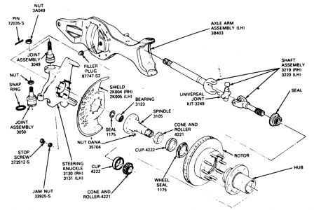
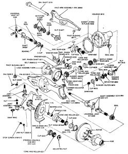
Fig. 1: Spindle, left shaft and joint installation for the Dana 44 and 50 front axles


https://www.2carpros.com/forum/automotive_pictures/52960_0900c1528004bc5f_1.jpg


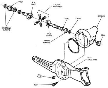
Fig. 2: Carrier and slip yoke, stub shaft installation on the Dana 44 and 50 IFS1.Raise and support the front end on jackstands.
2.Remove the front wheels.
3.Remove the calipers.
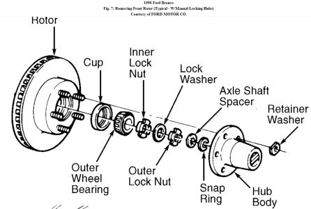
4.Remove the hub/rotor assemblies.
5.Remove the nuts retaining the spindle to the steering knuckle. Tap the spindle with a plastic mallet to remove it from the knuckle.
6.Remove the splash shield.
7.On the left side, pull the shaft from the carrier, through the knuckle.
8.On the right side, remove and discard the keystone clamp from the shaft and joint assembly and the stub shaft. Slide the rubber boot onto the shaft and pull the shaft and joint assembly from the splines of the stub shaft.
9.Place the spindle in a soft-jawed vise clamped on the second step of the spindle.
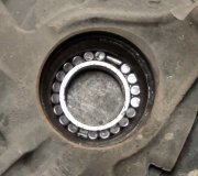
10.Using a slidehammer and bearing puller, remove the needle bearing from the spindle.
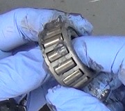
11.Inspect all parts. If the spindle is excessively corroded or pitted it must be replaced. If the U-joints are excessively loose or don't move freely, they must be replaced. If any shaft is bent, it must be replaced.
12.Clean all dirt and grease from the spindle bearing bore. The bore must be free of nicks and burrs.

To install:

13.Insert a new spindle bearing in its bore with the printing facing outward. Drive it into place with drive T80T-4000-S for F-150 and Bronco and F-250, or T80T-4000-R for the F-350, or their equivalents. Install a new bearing seal with the lip facing away from the bearing.
14.Pack the bearing and hub seal with grease. Install the hub seal with a driver.
15.Place the thrust washer on the axle shaft.
16.Place a new slender on the axle shaft.
17.Install the rubber V-seal on the slinger. The seal lip should face the spindle.
18.Install the plastic spacer on the axle shaft. The chamfered side of the spacer should be inboard against the axle shaft.
19.Pack the thrust face of the seal in the spindle bore and the V-seal on the axle shaft with heavy duty, high temperature, waterproof wheel bearing grease.
20.On the right side, install the rubber boot and new keystone clamps on the stub shaft and slip yoke. The splines permit only one way of meshing so you'll have to properly align the missing spline in the slip yoke with the gapless male spline on the shaft. Slide the right shaft and joint assembly into the slip yoke, making sure that the splines are fully engaged. Slide the boot over the assembly and crimp the keystone clamp.
21.On the left side, slide the shaft and joint assembly through the knuckle and engage the splines in the carrier.
22.Install the splash shield and spindle on the knuckle. Tighten the spindle nuts to 60 ft. lbs.
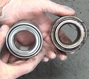
23.Install the rotor on the spindle. Install the outer wheel bearing into the cup. Make sure that the grease seal lip totally encircles the spindle.
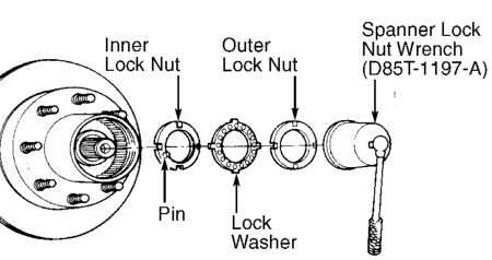
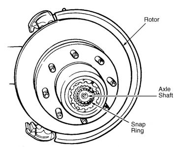
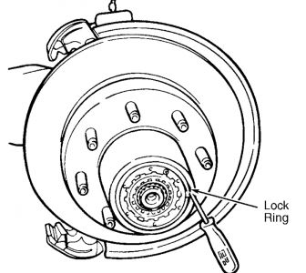
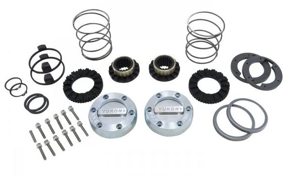
24.Install the wheel bearing, locknut, thrust bearing, snapring and locking hubs.
25.Install the caliper.


https://www.2carpros.com/forum/automotive_pictures/52960_0900c1528004bc9f_1.jpg


1.Raise and support the front end on jackstands placed under the radius arms.
2.Remove the wheels.
3.Remove the calipers and wire them out of the way. Don't disconnect the brake lines.
4.Support the axle arm with a jack and remove the upper coil spring retainers.
5.Lower the jack and remove the coil springs, spring cushions and lower spring seats.
6.Disconnect the shock absorbers at the radius arms and upper mounting brackets.
7.Remove the studs and spring seats at the radius arms and axle arms.
8.Remove the bolts securing the upper attachment to the axle arm and the lower attachment to the axle arm.
9.Disconnect the vent tube at the housing. Remove the vent fitting and install a 1/8 inch; pipe plug.
10.Remove the pivot bolt securing the right side axle arm to the crossmember. Remove and discard the boot clamps and remove the boot from the shaft. Remove the right drive axle assembly and pull the axle shaft from the slip shaft.
11.Support the housing with a floor jack. Remove the bolt securing the left side axle assembly to the crossmember. Remove the left side drive axle assembly.
12.Installation is, basically, a reversal of the removal procedure. Always use new boot clamps. Observe the torque values listed in of this information.
à † Driveshaft-to-flange: 15-20 ft.lb.
à † Spindle connecting rod-to-knuckle: 70-100 ft.lb.
Was this
answer
helpful?
Yes
No
+1
Sunday, October 26th, 2008 AT 6:41 PM
Tiny
CHEERS2UUU
  • MEMBER
  • 1 POST
  • 1996 FORD BRONCO
  • V8
  • 4WD
  • AUTOMATIC
  • 145,000 MILES
Drive train axles bearings problem. V8 four wheel drive automatic 145,000 miles.

I am trying to replace the outer wheel bearings on my truck. I have gotten as far as the wheel bearing itself but cannot figure out how to get the old one out. Can you please give me some direction and direct me to a schematic diagram of the front end of the Bronco? Thanks
Was this
answer
helpful?
Yes
No
Tuesday, January 10th, 2017 AT 11:39 AM (Merged)
Tiny
MERLIN2021
  • MECHANIC
  • 17,250 POSTS
Removal (four wheel drive with automatic and manual locking hubs) 1. Raise vehicle, and support with safety stands. Remove wheel assembly and caliper. On vehicles with automatic locking hubs, separate hub cap from hub body assembly by removing 5 Torx (T25) head cap screws. Remove cap. Do not drop spring, ball bearing, bearing race or retainer. 2. Remove rubber seal and seal bridge from retainer ring space. Remove retainer ring by squeezing ends together. Remove hub body assembly. Remove "C" washer and splines spacer from spindle. On vehicles with manual locking hubs, separate hub cap from hub body assembly by removing six Allen head screws. 3. Remove snap ring attaching hub body assembly to spindle. Remove lock ring seated in groove of hub. See Fig. 8 . Remove hub body assembly. If hub body does not come out easily, install two hub cap screws into hub body, and pull hub body out of hub. 4. On vehicles with automatic locking hubs, use spanner lock nut wrench (D85T-1197-A) to remove outer lock nut. See Fig. 9 . Remove lock washer. Using spanner lock nut wrench, remove inner lock nut. Remove outer wheel bearing and rotor. 5. On vehicles with manual locking hubs, use spanner lock nut wrench (T86T-1197-A) to remove wheel bearing adjusting nut. Remove outer wheel bearing, and then rotor. Installation 1. On vehicles with automatic locking hubs, install rotor and outer wheel bearing. Install inner lock nut. While rotating disc back and forth, seat bearing by using Spanner Lock Nut Wrench (D85T-1197-A) to tighten inner lock nut to 50 ft. lbs. (68 N.m). Back off inner lock nut, and re-tighten to 30-40 ft. lbs. (41-54 N.m). 2. Install lock washer so key is in spindle groove. Tighten inner lock nut to engage lock nut pin in nearest lock washer hole. Install outer lock nut, and tighten to 160-205 ft. lbs. (217-278 N.m). Spindle end play should be less than .004" (.10 mm). 3. On vehicles with manual locking hubs, install rotor and outer wheel bearing. Install adjusting nut. While rotating disc back and forth, seat bearing by using spanner lock nut wrench (T86T-1197-A) to tighten adjusting nut to 70 ft. lbs. (95 N.m). 4. Back off adjusting nut 90 degrees, and re-tighten to 15-20 ft. lbs. (20-27 N.m). Spindle end play should be zero. To install remaining hub body components, reverse removal procedure. See Fig. 7 . NOTE: Hub nuts are right-hand thread on both sides. Each hub is stamped RH to show thread direction. Do not use power impact tools to remove or install hub nuts. Hub nuts will ratchet unless hub wrench (T88T-4252-
5/5/2010 ...


https://www.2carpros.com/forum/automotive_pictures/62217_h1_2.jpg


https://www.2carpros.com/forum/automotive_pictures/62217_h2_2.jpg


https://www.2carpros.com/forum/automotive_pictures/62217_h3_2.jpg


https://www.2carpros.com/forum/automotive_pictures/62217_R1_1.jpg


https://www.2carpros.com/forum/automotive_pictures/62217_r2_1.jpg

Was this
answer
helpful?
Yes
No
+4
Tuesday, January 10th, 2017 AT 11:39 AM (Merged)
Tiny
SHANE COOK
  • MEMBER
  • 1 POST
Thanks for the information, but my problem is that I have replaced everything and putting back together, but I do not have enough room on the spindle to put the spindle shaft spacer washer and C clamp. There is no room for the washer to slide back over the groove to put the C clamp. Why? Did the spindle move?
Was this
answer
helpful?
Yes
No
Tuesday, January 10th, 2017 AT 11:39 AM (Merged)
Tiny
KEN L
  • MASTER CERTIFIED MECHANIC
  • 42,878 POSTS
Hey Shane,

The spindle did not move, you must push the axle through from the backside. This will give you the room you need to get it back together.

Please let us know what you find so it will help others.

Best, Ken
Was this
answer
helpful?
Yes
No
+1
Tuesday, January 10th, 2017 AT 11:39 AM (Merged)
Tiny
BLACKPIRATE
  • MEMBER
  • 1 POST
  • 1987 FORD BRONCO
Drive Train Axles Bearings problem
V8 four wheel drive manual a lot of miles.

I have a few question if you do not mind.

1. Can I change the bearing without taking the trruck to a shop?

2. If I do one side should I do the other to keep things even?

3. Will I have to drop the front axle to get the hub off?

4. Does the bearing have to be pressed off and the the new one on?

I need help so that I can make the right moves on fixing the Black Pirate aka 1987 Ford Bronco.
Was this
answer
helpful?
Yes
No
Tuesday, January 10th, 2017 AT 11:39 AM (Merged)
Tiny
BLACKOP555
  • MECHANIC
  • 10,371 POSTS
You can do it yourself and all you have to do is jack it up to get the wheel and hub off. You will also need a special tool to remove the hub on your model not a basic socket and breaker bar. You will need a special hub nut spanner wrench, you have to push in and turn at the same time.

When re-torquing it be sure to turn the wheel constantly so the wheel bearing sits properly.
Was this
answer
helpful?
Yes
No
Tuesday, January 10th, 2017 AT 11:39 AM (Merged)
Tiny
4STEELERS
  • MEMBER
  • 1 POST
  • 1992 FORD BRONCO
Tires and wheel problem
V8 four wheel drive automatic.

I know I need new front wheel bearings for my vehicle, but could you tell me how to change them and what tools I might need?
Was this
answer
helpful?
Yes
No
Tuesday, January 10th, 2017 AT 11:39 AM (Merged)
Tiny
BLUELIGHTNIN6
  • MECHANIC
  • 16,542 POSTS
Do you have automatic or manual locking hubs?
Was this
answer
helpful?
Yes
No
Tuesday, January 10th, 2017 AT 11:39 AM (Merged)
Tiny
RMA
  • MEMBER
  • 1 POST
  • 1985 FORD BRONCO
Tires and Wheels problem
1985 Ford Bronco 6 cyl Four Wheel Drive Automatic

how many foot pounds need to be used to tighten the spindle nut (wheel bearing nut)?
Was this
answer
helpful?
Yes
No
-1
Monday, August 19th, 2019 AT 6:47 PM (Merged)
Tiny
JACOBANDNICKOLAS
  • MECHANIC
  • 108,170 POSTS
With manual locking hubs, install the outer wheel bearing locknut using 4 prong spindle nut spanner wrench, tool T86T-1197-A or equivalent. Tighten locknut to 150 ft. Lbs

Let me know if this helps.

Joe
Was this
answer
helpful?
Yes
No
Monday, August 19th, 2019 AT 6:47 PM (Merged)
Tiny
AUDIOSHOCKWAV
  • MEMBER
  • 1 POST
  • 1985 FORD BRONCO
Hello,
I have a 1985 full size bronco 4x4.
The front wheel bearings are loose, how do I tighten them up?
Do I need special tools?
Any help would be great
Thanks
Jeff
Was this
answer
helpful?
Yes
No
-1
Monday, August 19th, 2019 AT 6:47 PM (Merged)
Tiny
MIKE H R
  • MECHANIC
  • 3,094 POSTS
Jack the car up and wiggle the wheel. If loose the bearings can usually be replaced with most ordinary tools. After checking the looseness take the wheel off and check the retaining nut to see if it is on right.
If there is play in the wheel then the bearings need to be replaced.
Was this
answer
helpful?
Yes
No
+2
Monday, August 19th, 2019 AT 6:47 PM (Merged)
Tiny
BANEFIZZ
  • MEMBER
  • 1 POST
Most of my questions have been answered by reading above, but a plain simple answer to this would help a lot.

Background: Bought an 87 F-150 4x4 truck with manual Trans and man locking hubs. Its a project. Drove it onto the trailer to haul home as the steering was messed up. Imagine my surprise when tearing down the front end to install a 4" lift and working on the front axle I find that all but the bearings are gone in both front hubs.

Can anyone give me a parts list and maybe the part description to complete the hubs so I can finally put this sucker on the road.

Have spindles, rotors/brakes and the drive shafts work, it will drive(rear wheel only), but nothing to actually connect said shafts to the hubs. In other words I need all the greasy innards that make the wheels drive. Sorry I cant explain better, hopefully I am making this clearer than mud as to what I need.
Was this
answer
helpful?
Yes
No
Wednesday, January 22nd, 2020 AT 6:18 PM
Tiny
STEVE W.
  • MECHANIC
  • 12,961 POSTS
Sounds like someone removed the hubs because they were rusted or stuck. The easiest solution is to just go to a parts store or online and buy a replacement hub kit. It will come with all the missing parts you need. You normally buy the kit because then you have all matched parts because they don't sell the individual pieces.
Was this
answer
helpful?
Yes
No
Wednesday, January 22nd, 2020 AT 8:53 PM

Please login or register to post a reply.

Sponsored links