Good evening.
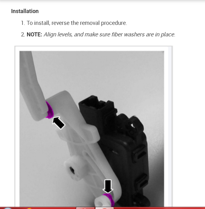
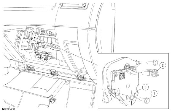
It is in the dash. The instrument cluster has to be removed to access. It is on the side of the heater case. I believe you can see it but not remove it without the dash removed.
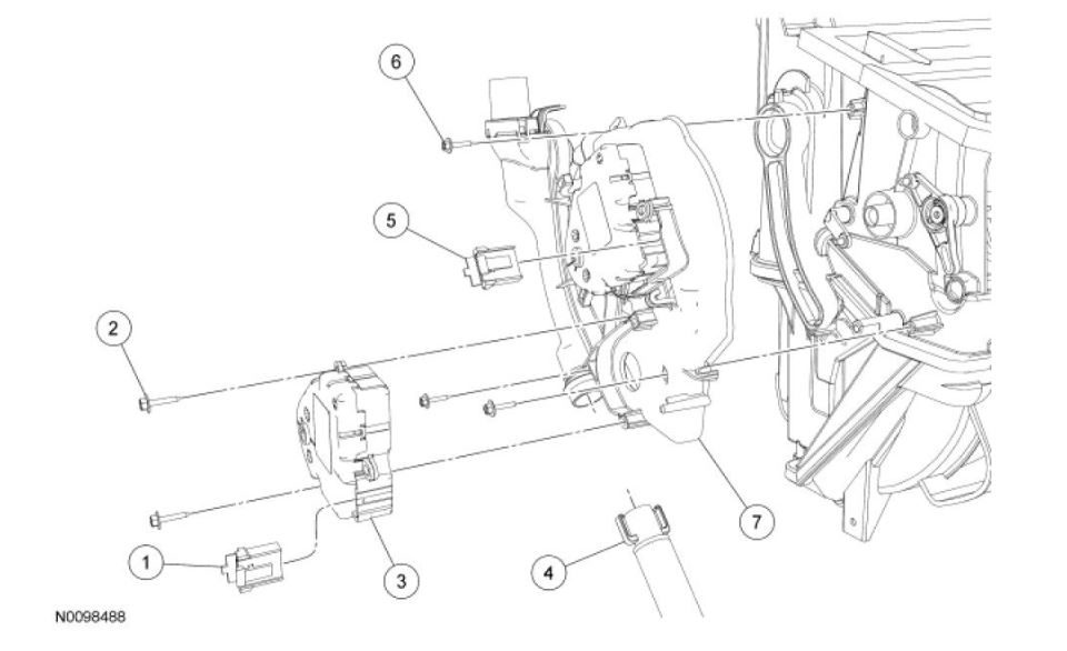
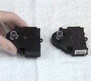
It is number 7 in the picture This is a very involved procedure. Are you planning on doing this job yourself?
Roy
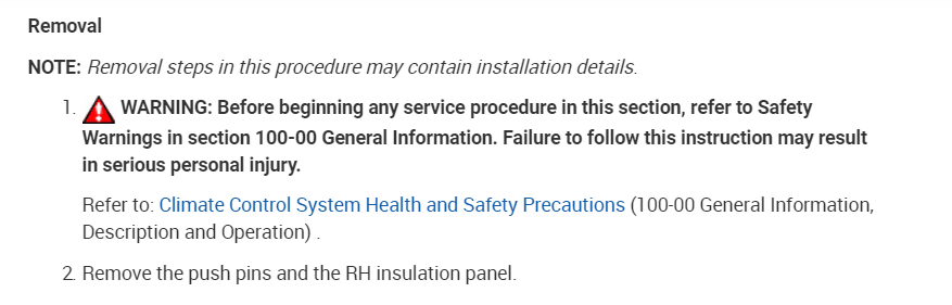
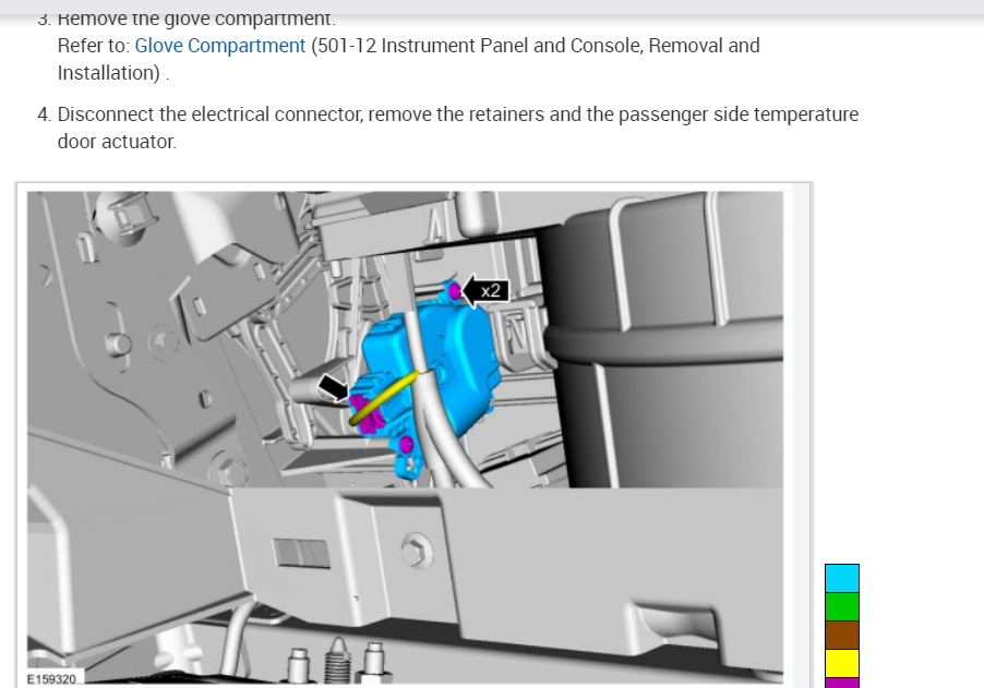
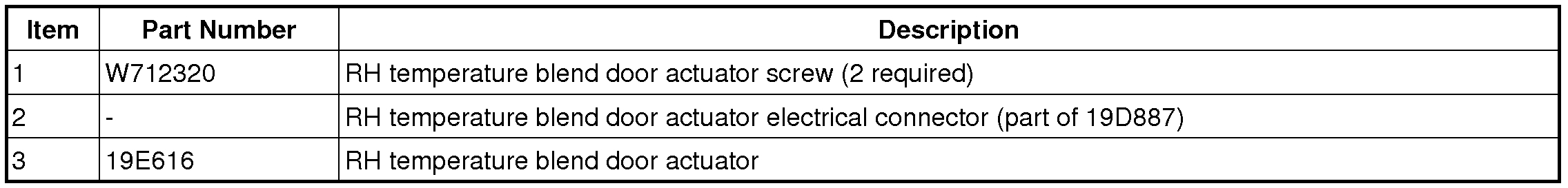
Removal and Installation
1. Remove the instrument panel. For additional information, refer to Instrument Panel and Console See: Dashboard / Instrument Panel > Removal and Replacement > Instrument Panel.
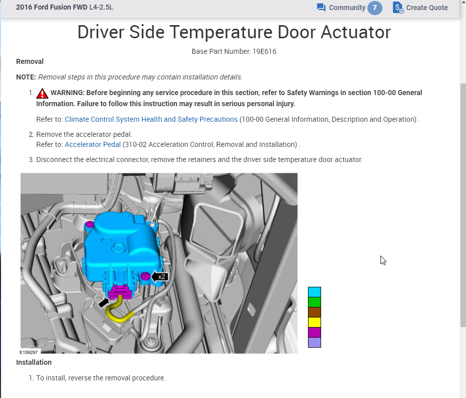
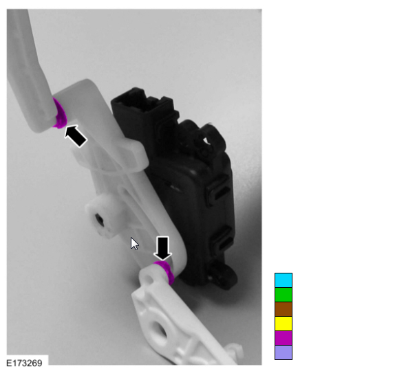
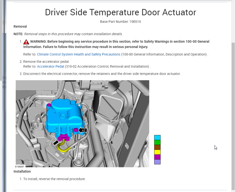
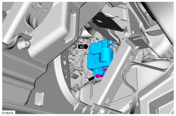
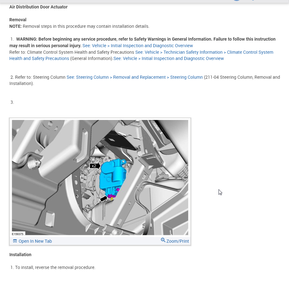
2. Disconnect the LH temperature blend door actuator electrical connector.
3. Remove the 2 LH temperature blend door actuator screws.
4. Remove the LH temperature blend door actuator.
5. Disconnect the in-vehicle temperature sensor aspirator hose connection.
6. Disconnect the DEFROST/PANEL/FLOOR mode door actuator electrical connector.
7. Remove the 3 DEFROST/PANEL/FLOOR mode door actuator and cam assembly screws.
8. Remove the DEFROST/PANEL/FLOOR mode door actuator and cam assembly.
9. To install, reverse the removal procedure.
10. NOTE: The purpose of the module actuator position calibration is to allow the HVAC module to reinitialize and calibrate the actuator stop points. To carry out calibration, carry out the following steps.
Remove the Smart Junction Box (SJB) fuse 15 for at least one minute.
11. NOTE: When the ignition switch is switched to the ON position, the HVAC module will initialize and calibrate the actuators. Calibration of the actuators will take approximately 30 seconds.
Reinstall SJB fuse 15. Turn the ignition switch to the ON position and wait 30 seconds before verifying correct DEFROST/PANEL/FLOOR operation.
The procedure for removing the dash.
Nstrument Panel
Removal and Installation
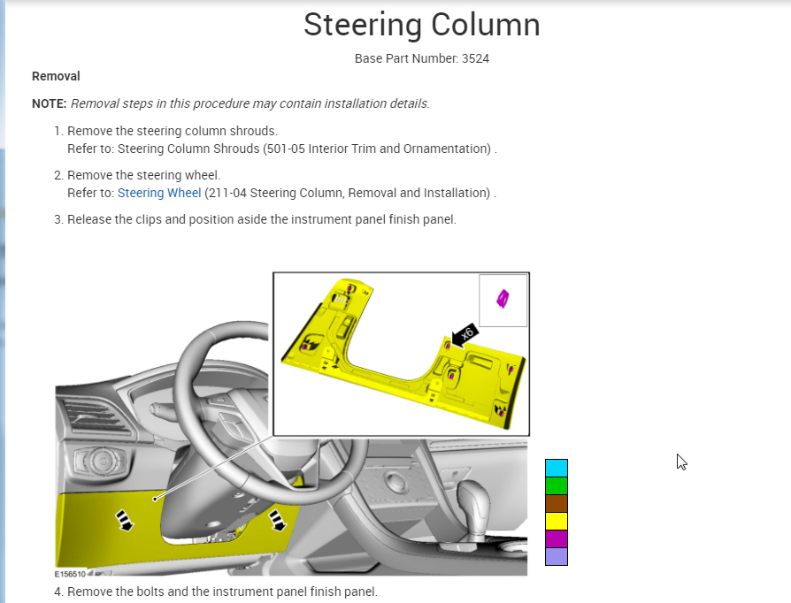
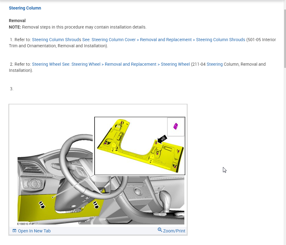
1. Remove the steering wheel. For additional information, refer to Steering Column See: Steering Wheel > Removal and Replacement > Steering Wheel.
2. Remove the floor console. For additional information, refer to Console - Floor, Fusion, Milan See: Console > Removal and Replacement > Console - Floor or Console - Floor, MKZ See: Console > Removal and Replacement > Console - Floor.
3. Remove the selector lever or the gearshift lever. For additional information, refer to See: Shifter A/T > Removal and Replacement.
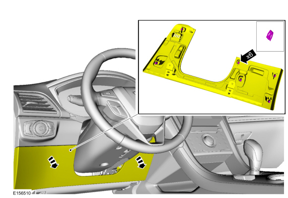
4. Remove the LH and RH instrument panel side finish panels.
- Pull the sides of the instrument panel side finish panels away from the instrument panel to release the retaining tabs.
5. Remove the LH and RH weatherstrips from the front door openings near the instrument panel.
6. Remove the LH and RH A-pillar trim panels. For additional information, refer to Interior Trim and Ornamentation See: Trim Panel > Removal and Replacement.
7. Remove the LH and RH lower cowl panels. For additional information, refer to Interior Trim - Exploded View in Interior Trim and Ornamentation See: Trim Panel > Removal and Replacement > Interior Trim - Exploded View.
8. If equipped, remove the RH lower instrument panel insulator.
9. Disconnect the 2 electrical connectors located at the LH lower cowl.
ImageOpen In New TabZoom/Print
10. Disconnect the small gray and the black electrical connectors from the Smart Junction Box (SJB).
ImageOpen In New TabZoom/Print
11. Remove the 2 screws and position the hood release handle aside.
ImageOpen In New TabZoom/Print
12. Disconnect the bulkhead electrical connector and the antenna cable located at the RH lower cowl. If equipped, disconnect the satellite antenna.
ImageOpen In New TabZoom/Print
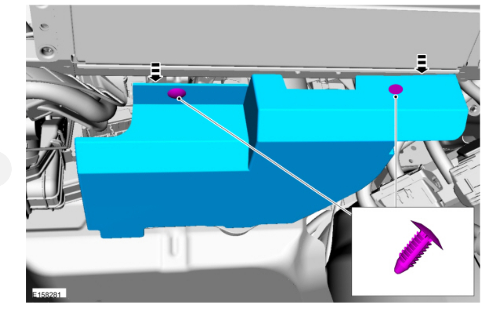
13. Fully lower the glove compartment door and disconnect the 2 A/C electrical connectors.
ImageOpen In New TabZoom/Print
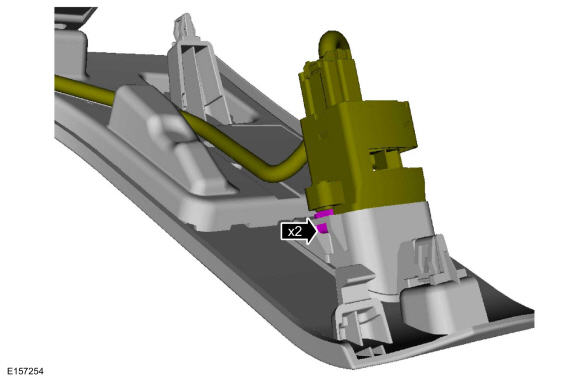
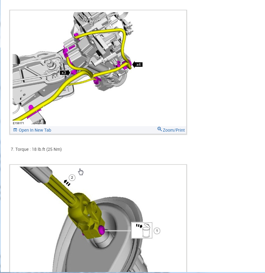
14. Disconnect the electrical connector and the 2 wire harness retainers located on the floor between the front seats.
ImageOpen In New TabZoom/Print
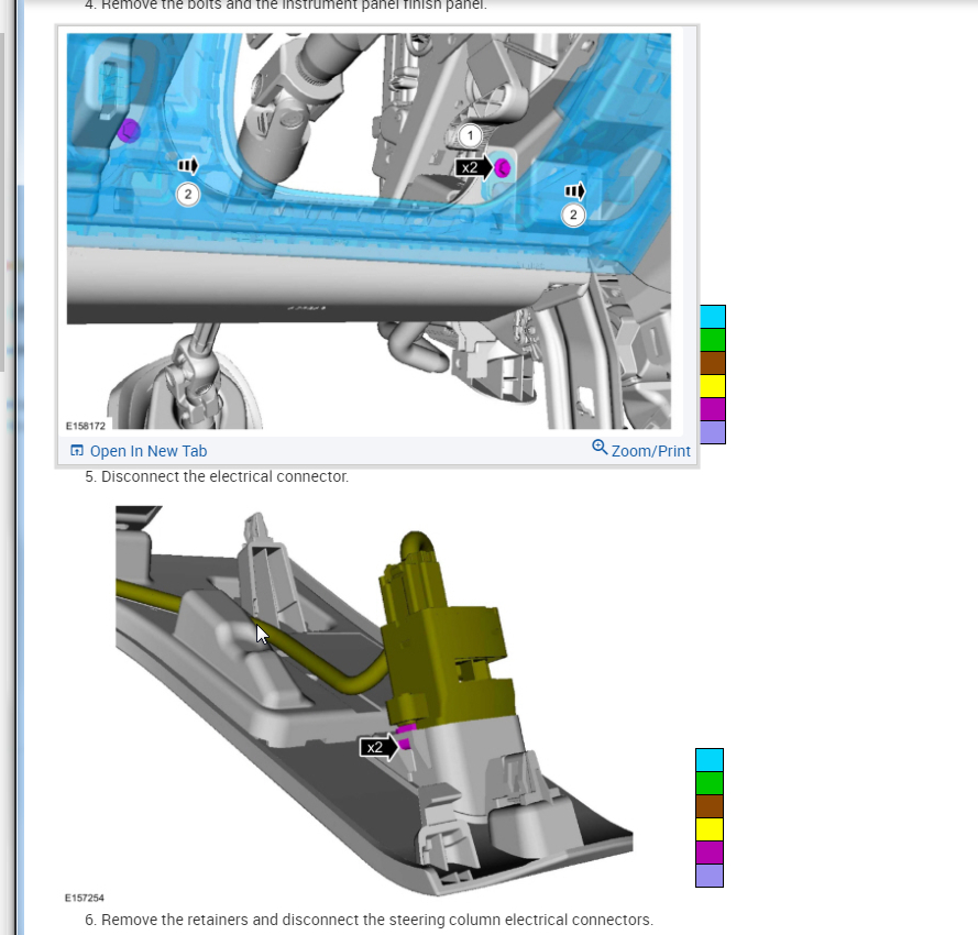
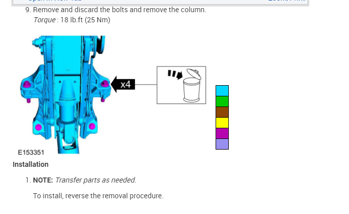
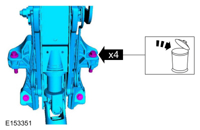
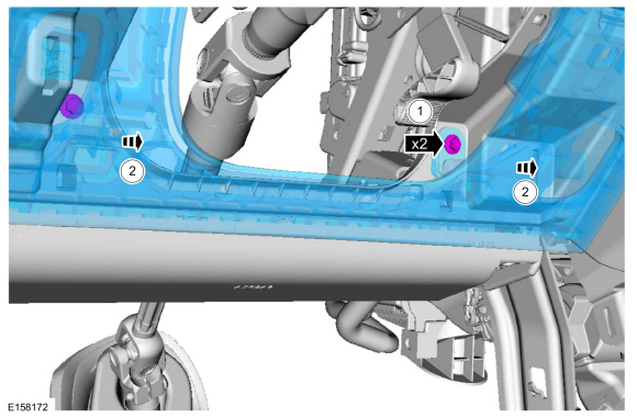
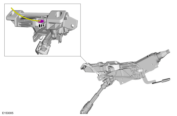
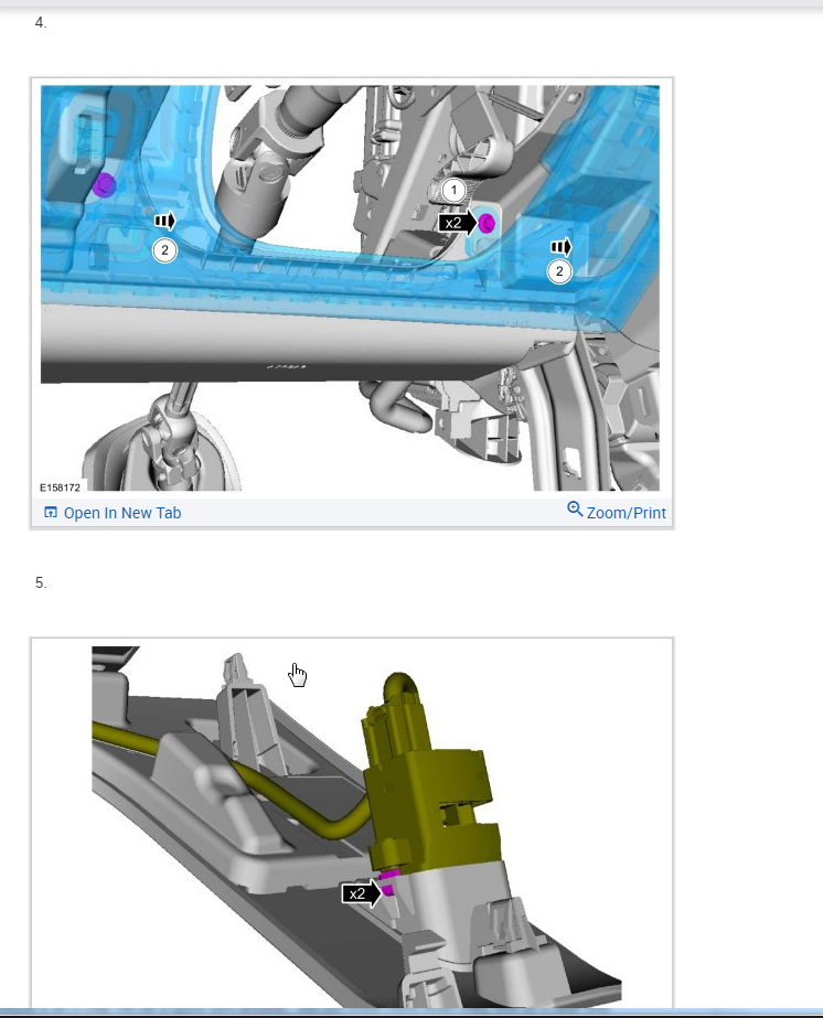
15. Remove the 2 nuts and position the steering column pinch bolt cover aside.
ImageOpen In New TabZoom/Print
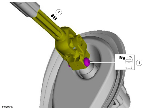
16. Remove and discard the steering column shaft bolt.
- To install, use a new steering column shaft bolt and tighten to 20 Nm (177 lb-in).
ImageOpen In New TabZoom/Print
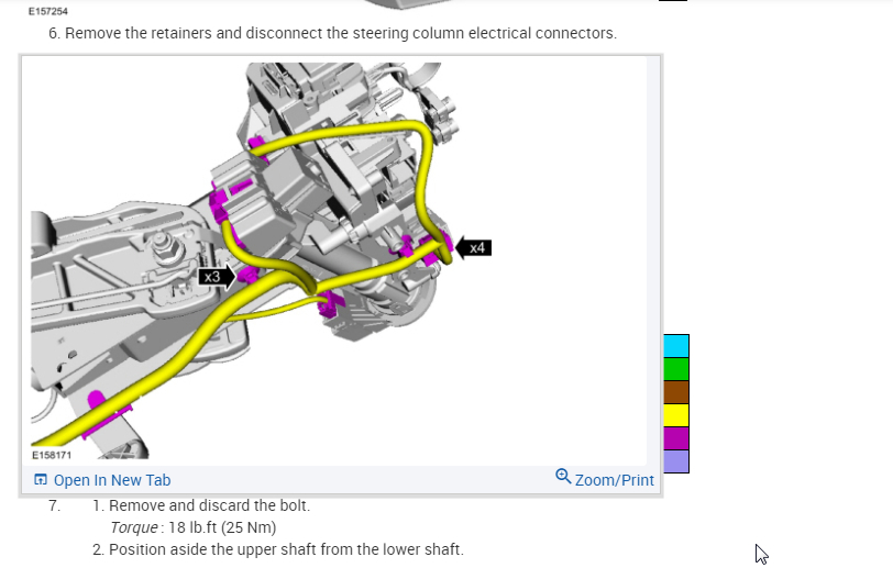
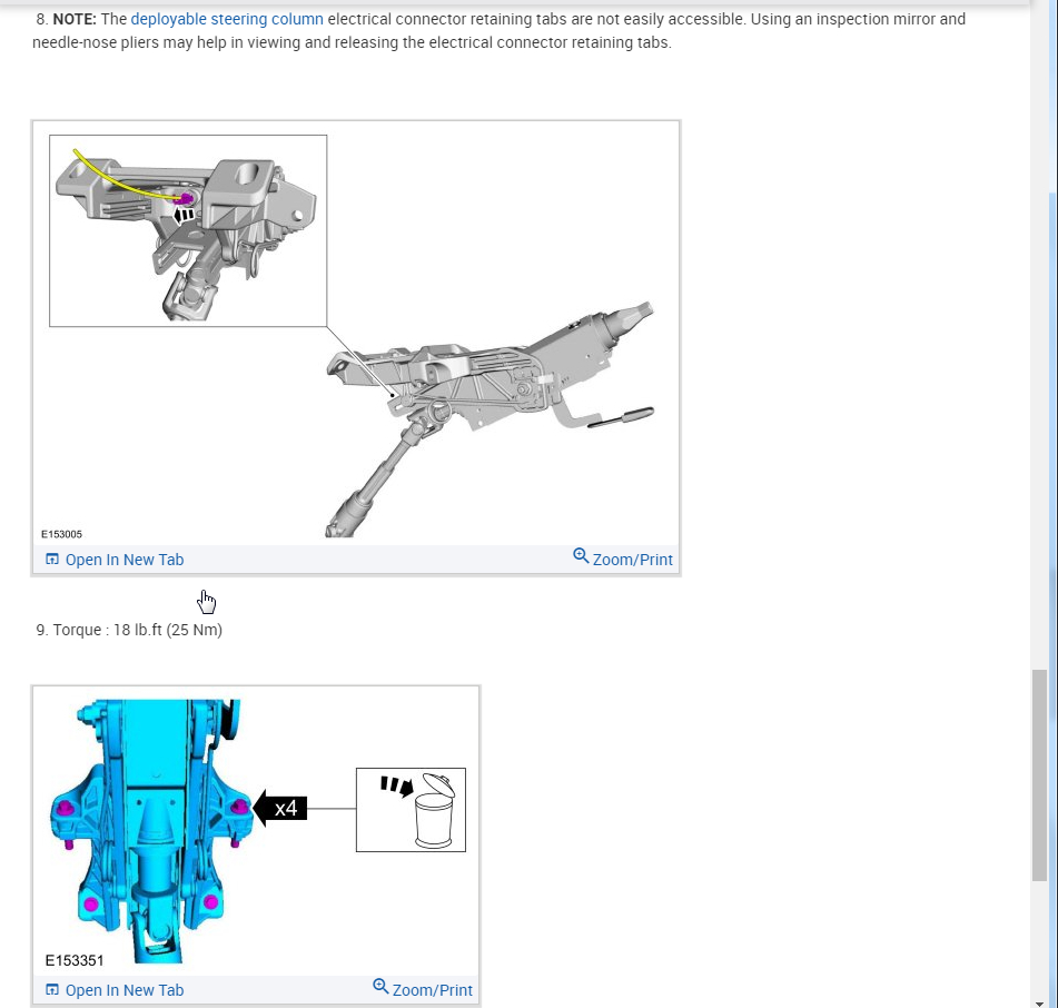
17. NOTE: Index-mark the steering column shaft position to the steering gear for reference during installation.
Detach the upper steering column shaft from the steering column.
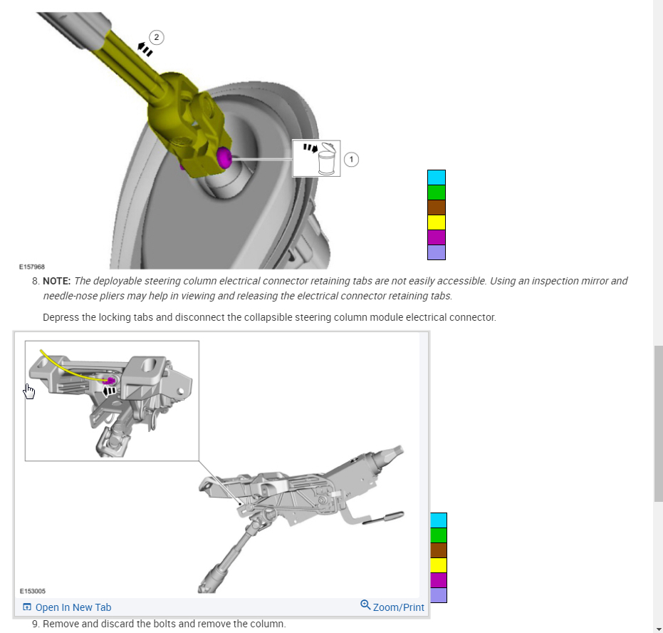
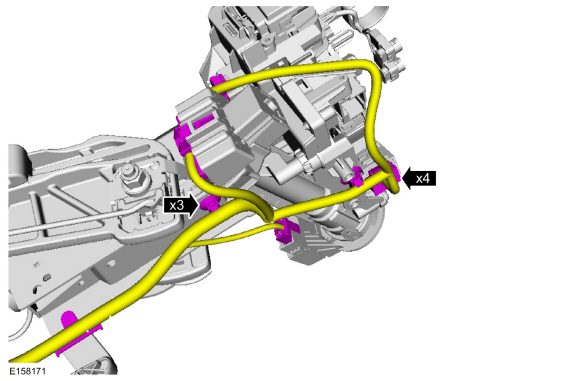
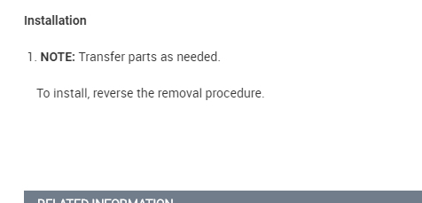
18. Disconnect the in-vehicle temperature sensor aspirator hose from the heater core and evaporator core housing, if equipped, in the following sequence.
1. Separate the aspirator hose retaining clips away from the heater core and evaporator core housing.
2. Pull the aspirator hose away from the heater core and evaporator core housing.
ImageOpen In New TabZoom/Print
19. Remove the Instrument Cluster (IC). For additional information, refer to Instrumentation, Message Center, and Warning Chimes See: Instrument Cluster / Carrier > Removal and Replacement > Instrument Panel Cluster (IPC).
20. Through the IC opening, remove the 2 IC opening bolts.
- To install, tighten to 23 Nm (17 lb-ft).
21. Remove the 3 instrument panel center support bolts.
- To install, tighten to 20 Nm (177 lb-in).
22. Remove the LH and RH instrument panel lower bolts from the outer sides of the instrument panel.
- To install, tighten to 8 Nm (71 lb-in).
23. NOTICE: To avoid damaging the instrument panel, the aid of an assistant is required to carry out this step.
NOTICE: Make sure that all electrical connectors and wiring are not hindered before removing the instrument panel or damage to the components may occur.
Remove the instrument panel.
- Through the instrument panel side finish panel openings, remove the 3 instrument panel side bolts.
- To install, tighten to 23 Nm (17 lb-ft).
24. NOTICE: To avoid damaging the instrument panel, the aid of an assistant is required when positioning the instrument panel to the vehicle.
NOTICE: Make sure that all electrical connectors and wiring are correctly routed when installing the instrument panel or damage to the components may occur.
To install, reverse the removal procedure.
Image (Click to make bigger)
Wednesday, October 14th, 2020 AT 12:50 PM
(Merged)