2001 Chevy Venture Power Window / Wipers

Tiny
MEMOREX
  • MEMBER
  • 2001 CHEVROLET VENTURE
  • 6 CYL
  • 2WD
  • AUTOMATIC
  • 145,000 MILES
Hi I have some small Problems with this Vehicle.

No Cold AC
Passenger Power Window
Windshield Wiper Motor

With the Passenger Side Power Window.

It will go down but not up.

I placed a Multimeter onto the Motor Wires and get 12-14v on the down on both Switches but anywhere between 0 and 4v on the UP with both switches.

My question what switch do you think needs replacing the Passenger is my Guess but as these switches are interconnected what would be your guess?

My Wiper motor only works on High Speed although I do hear a Click if I rotate the slow speed switch coming from the motor area with the hood up.

Would you say that would be a Motor Issue.

Rob.
Wednesday, July 28th, 2010 AT 4:32 PM

13 Replies

Tiny
KHLOW2008
  • MECHANIC
  • 41,815 POSTS
Hi memorex,

Thank you for the donation.

Here are some test that you can carry out to determine the cause.

TEST C: PASSENGER'S SIDE POWER WINDOW INOPERATIVE
1.If description and operation has been reviewed, go to next step.

2.Verify passenger's side power window is inoperative. If passenger's side power window is inoperative, go to next step.

3.Disconnect passenger's side power window switch 8-pin harness connector. Turn ignition switch to RUN position. Using test light connected to ground, probe passenger's side power window switch harness connector terminal "F" (Yellow wire). See Fig. 1 . If test light illuminates, go to next step. If test light does not illuminate, go to step 13 .


https://www.2carpros.com/forum/automotive_pictures/192750_PowerWindow01VentureFig01_1.jpg


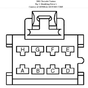
4.Connect test light between passenger's side power window switch harness connector terminals "D" (Tan wire) and "H" (Light Blue wire). Using power window master switch, press passenger's side window switch to UP and DOWN positions. If test light illuminates in both positions, go to next step. If test light does not illuminate in either position, go to step 6 .

5.Connect passenger's side power window switch harness connector. Disconnect passenger's side power window motor 2-pin harness connector. Connect test light between passenger's side power window motor harness connector terminals "A" (Dark Blue wire ) and "B" (Brown wire). Press passenger's side power window switch to UP and DOWN positions. If test light does not illuminate either position, go to step 8 . If test light illuminates in both positions, go to step 10 .

6.Check for open in Light Blue wire between power window master switch and passenger's side power window switch. If problem does not exist, go to next step. If problem exists, repair as necessary. After repair, go to step 17 .

7.Check for open in Tan wire between power window master switch and passenger's side power window switch. If problem does not exist, go to step
11 . If problem exists, repair as necessary.
After repair, go to step 17 .

8.Check for open in Dark Blue wire between power window master switch and passenger's side power window switch. If problem does not exist, go to next step. If problem exists, repair as necessary. After repair, go to step 17 .

9.Check for open in Brown wire between power window master switch and passenger's side power window switch. If problem does not exist, go to step
12 . If problem exists, repair as necessary. After repair, go to step 17 .

10.Check passenger's side power window motor harness connector for poor connections or loose terminals. If problem does not exist, go to step
14 . If problem exists, repair as necessary. After
repair, go to step 17 .

11.Check power window master switch harness connector for poor connections or loose terminals. If problem does not exist, go to step 15 . If problem exists, repair as necessary. After repair, go to step 17 .

12.Check passenger's side power window switch harness connector for poor connections or loose terminals. If problem does not exist, go to step
16 . If problem exists, repair as necessary. After
repair, go to step 17 .

13.Repair open in Yellow wire between passenger's side power window switch and instrument panel fuse block. After repair, go to step 17 .

14.Replace passenger's side power window motor. After repair, go to step 17 .

15.Replace power window master switch. After repair, go to step 17 .

16.Replace passenger's side power window switch. After repair, go to next step.

17.Operate system to verify repair. If problem does not exist, system is okay. If problem exists, go to step 2 .

TEST C: FRONT WIPERS INOPERATIVE IN ONE OR MORE MODES
1.If description and operation has been reviewed, go to next step.

2.Turn ignition switch to RUN position. Turn multifunction switch through all switch positions. If front wipers do not operate normally in all modes, go to next step. If front wipers operate normally in all modes, diagnose intermittent condition.

3.Turn ignition switch to LOCK position. Disconnect multifunction switch 48-pin harness connector C201. Harness connector C201 is located to left side of steering column, near base. Disconnect front wiper motor 6-pin harness connector. Check for open, high resistance or short to ground in Purple wire between front wiper motor and multifunction switch. If problem does not exist, go to next step. If problem exists, repair as necessary. After repair, go to step
13 .

4.Check for open, high resistance or short to ground in Gray wire between front wiper motor and multifunction switch. If problem does not exist, go to next step. If problem exists, repair as necessary. After repair, go to step 13 .

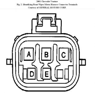
5.Check for open, high resistance or short to ground in Dark Green wire between front wiper motor and multifunction switch. See Fig. 2 and Fig. 3. If problem does not exist, go to next step. If problem exists, repair as necessary. After repair, go to step
13 .


https://www.2carpros.com/forum/automotive_pictures/192750_Wiper01VentureFig02_1.jpg


https://www.2carpros.com/forum/automotive_pictures/192750_Wiper01VentureFig03_1.jpg


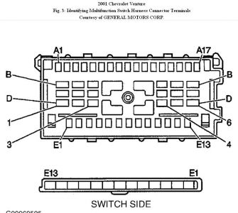
6.Measure resistance between multifunction switch pigtail harness connector C201 terminals E3 (Dark Green wire) and E9 (Yellow wire) - (component side). See Fig. 3 . Turn wiper portion of multifunction switch to MIST, LO and HI positions. If resistance is less than 2 ohms, go to next step. If resistance is 2 ohms or more, go to step 10 .

7.Measure resistance between multifunction switch pigtail harness connector C201 terminals E3 (Dark Green wire) and E9 (Yellow wire) - (component side). Turn multifunction switch through all DELAY positions. Resistance should be 39-680 k/ohms. If resistance is as specified, go to next step. If resistance is not as specified, go to step 10 .

8.Measure resistance between multifunction switch pigtail harness connector C201 terminals E3 (Dark Green wire) and E9 (Yellow wire) - (component side). Turn wiper portion of multifunction switch to MIST, LO and HI positions. Resistance should be 24 k/ohms. If resistance is as specified, go to next step. If resistance is not as specified, go to step 10 .

9.Connect multifunction switch harness connector C201. Connect front wiper/washer motor harness connector. Turn ignition switch to RUN position. Turn wiper portion of multifunction switch to HI position. If front wipers operate normally, go to step
11 . If front wipers do not operate normally, go to step 12 .

10.Replace multifunction switch. After repair, go to step 13 .

11.Replace front wiper drive system module. After
repair, go to step 13 .

12.Replace front wiper motor. After repair, go to next step.

13.Operate system to verify repair. If problem does not exist, system is okay. If problem still exists, go to step 3 .

As to the A/C not cold, get the low and high pressure readings and let me know what they are. Did you check if the compressor is engaging?
Was this
answer
helpful?
Yes
No
Thursday, July 29th, 2010 AT 8:24 AM
Tiny
MEMOREX
  • MEMBER
  • 12 POSTS
Hi I don't think it is Engaging at the moment.

Hoping it's not a Compressor failure.

Rob.
Was this
answer
helpful?
Yes
No
Thursday, July 29th, 2010 AT 5:31 PM
Tiny
MEMOREX
  • MEMBER
  • 12 POSTS
OK.

Checked the Light Blue Wire and the Tan wires. All ok.

Here's my question?

When I used a local Ground (KEY in ignition) I got 12v on both sides when I hooked up my meter.

When I metered across both wires I only get 12v when the Master Switch is set to Open (Lower) the Passenger Window. There is like 0.5v when I try to close (Lift) the Window.

I checked continuity between the Blue and Tan wires and that's fine so as a result I have to suspect the Master Switch is at Fault.

Thanks for the Diagram and color codes that was invaluable.

Tomorrow I move onto the Wiper Moter.

Rob.
Was this
answer
helpful?
Yes
No
Thursday, July 29th, 2010 AT 6:22 PM
Tiny
MEMOREX
  • MEMBER
  • 12 POSTS
OK you posted earlier :

Check the Dark Blue and Brown Wires between the switches for open circuit.

Correct me if I am wrong but these are the Motor Switches and therefore should be open circuit between the Master / Slave Switch as these motors are NOT connected together.

To add to my Post earlier :

When I use a common Ground (Key in Ignition) both the TAN and Light Blue wires work in both positions off the Master Switch.

When I connect a meter across the TAN and Light Blue Wires only 1 wire energizes the other gives me 0.5v. As I was expecting a +12 across one way and a -12v across the other way do you think there may be a grounding issue?

Rob.
Was this
answer
helpful?
Yes
No
Thursday, July 29th, 2010 AT 6:51 PM
Tiny
KHLOW2008
  • MECHANIC
  • 41,815 POSTS
Sorry for the delay in replying.

If the comptressor is not engaging, it could be anything from power supply to freon pressure.

Disconnect the compressor clutch wire and apply battery voltage to the clutch to see if it click. If yes, then we need to check the power supply and prsssure, not a fault with the compressor clutch.

When the master switch is operated, you get 12 volts across Light Blue and Tan wires indicating the switch is working correctly.

The up function is not working correctly indicating the master switch contact is bad and there is no continuity inside the switch.

It you had followed the the repair procedures, Step 4, 6, 7, 11 and 15. It indicates the master switch is faulty.

You are correct about 12 V and -12 V when reversing the switch position when voltmeter is connected between the LT Blue and Tan wires.

It is a grounding issue but you mentined in your earlier test that there is 12 V in the down direction, so it is not an external ground but the internal circuit of the mater switch that is bad not allowing the circuit to be grounded when the up function is used.
Was this
answer
helpful?
Yes
No
Saturday, July 31st, 2010 AT 9:12 AM
Tiny
MEMOREX
  • MEMBER
  • 12 POSTS
OK I put a Pressure test on the Low Pressure line and it indicated low Refrigerant Pressure.

So I put some in and discovered that after a few minutes the pressure would drop so I must have a small leak somewhere.

I noticed when I was adding Refrigerant that the engine seemed to speed up and I assume that was the Compressor kicking in.

I didn't notice any Cold Air Blowing though so I hope that the Problem might be a small leak and not a Compressor Issue.

Any Ideas.

Rob.
Was this
answer
helpful?
Yes
No
Saturday, July 31st, 2010 AT 6:24 PM
Tiny
KHLOW2008
  • MECHANIC
  • 41,815 POSTS
Further testings would have to be done to get the required information tounderstand what is wrong better. If it is a leak, it can be from anything from joints to the compressor. If it is a leak, it most probably would be indicated by presence of oil. Check joints and components for signs of oil, usually slightly damp.

What was the presure before topping up the freon?

Can you get the low and high presure readings with the engine running and A/C turned on?
Was this
answer
helpful?
Yes
No
Saturday, July 31st, 2010 AT 10:56 PM
Tiny
MEMOREX
  • MEMBER
  • 12 POSTS
Low about was 15 psi.

When I was refiling it went up to 35 psi and at that time I heard the engine speed increase or the compressor kicking in.

But after about 10 Minutes it would drop without giving any cold air.

Whats the Pressure Capacity of the High Pressure Valve.

My Tester is one which attaches to a refill bottle and have a max of 200 psi.

Rob.
Was this
answer
helpful?
Yes
No
Monday, August 2nd, 2010 AT 7:02 PM
Tiny
KHLOW2008
  • MECHANIC
  • 41,815 POSTS
The high pressure should be around 200 psi. You cannot use the can to test, first it would not match and secondly it is not designed for such as the high pressure can go up to more than 300 psi if something is wrong.

You would need specified pressure tester.

The normal operating pressure of the low side should be around 30 psi at idling. Without starting the engine, check the low pressure, it should be around 90 psi.
Was this
answer
helpful?
Yes
No
Tuesday, August 3rd, 2010 AT 7:42 AM
Tiny
MEMOREX
  • MEMBER
  • 12 POSTS
Erm Low pressure didnt even register with the Engine Off !

Any Ideas.

Rob.
Was this
answer
helpful?
Yes
No
Wednesday, August 4th, 2010 AT 11:12 AM
Tiny
KHLOW2008
  • MECHANIC
  • 41,815 POSTS
Either the meter is bad or there is no pressure in the system. That could mean a bad leak somewhere and whatever freon that you have topped up is now in the atmosphere.

You would need to check and rectify the leakage first.
Was this
answer
helpful?
Yes
No
Wednesday, August 4th, 2010 AT 12:46 PM
Tiny
MEMOREX
  • MEMBER
  • 12 POSTS
Yeah kinda thought as Much.

Hopefully it's a Leak and not the Compressor.

Thanks

Rob.
Was this
answer
helpful?
Yes
No
Wednesday, August 4th, 2010 AT 11:13 PM
Tiny
KHLOW2008
  • MECHANIC
  • 41,815 POSTS
If it is a leak in the condenser or cooling coil(evaporator) it ia not as cheap as a leak at joints or hoses.

Good luck.
Was this
answer
helpful?
Yes
No
Thursday, August 5th, 2010 AT 7:48 AM

Please login or register to post a reply.

Sponsored links