Welcome to 2CarPros.
The first set of directions will relate to removal. The attached pictures correlate with the directions. Check out the diagrams (Below)
ENGINE REMOVAL
Engine Replacement
Tools Required
* J41798 Engine Lifting Brackets
* J21366 Converter Holding Strap
* J42371 Clutch Line Removal Tool
* J5824-01 Clutch Alignment Tool
Removal Procedure
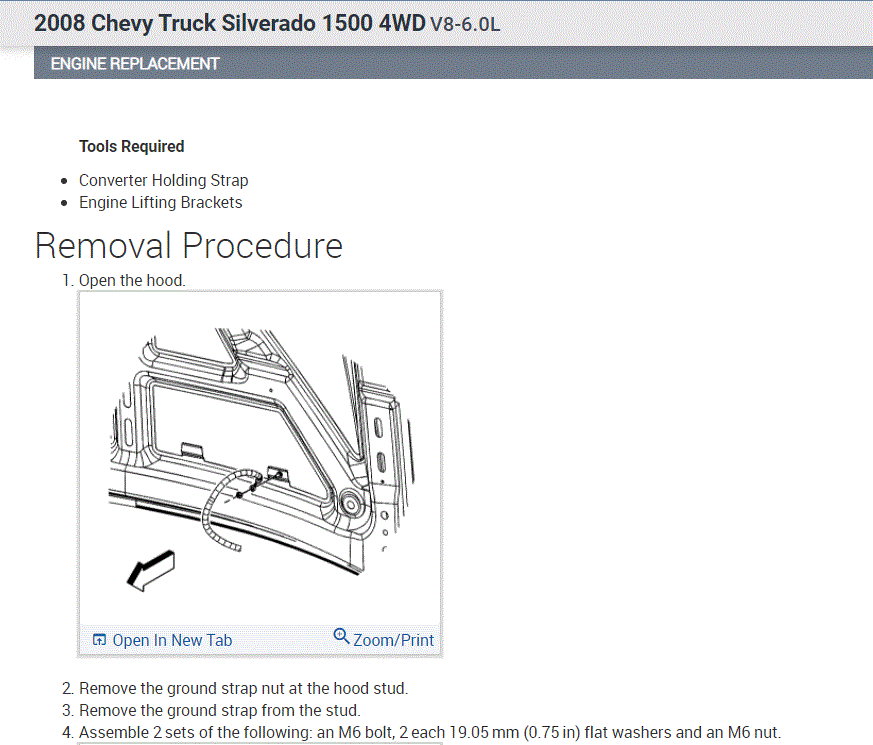
1. Open the hood.
2. Place fender covers over both fenders.
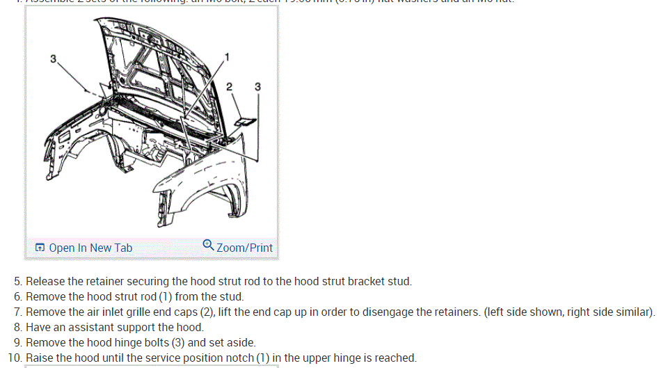
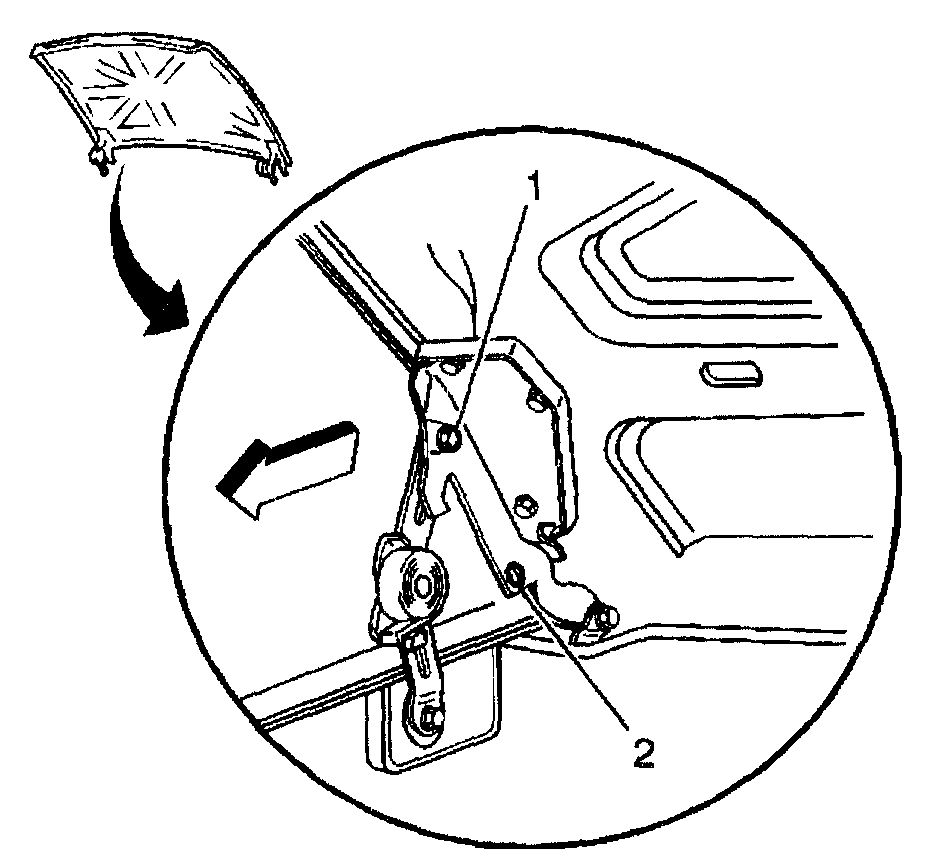
3. Raise the hood to the service position, perform the following:
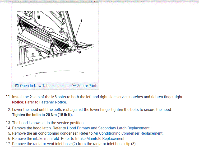
3.1. Remove the hood hinge bolts (1).
3.2. Raise the hood until vertical.
3.3. Install the hood hinge bolts until snug in the service position (2).
4. Remove the air conditioning (A/C) compressor.
5. Remove the radiator support.
6. Remove the engine sight shield.
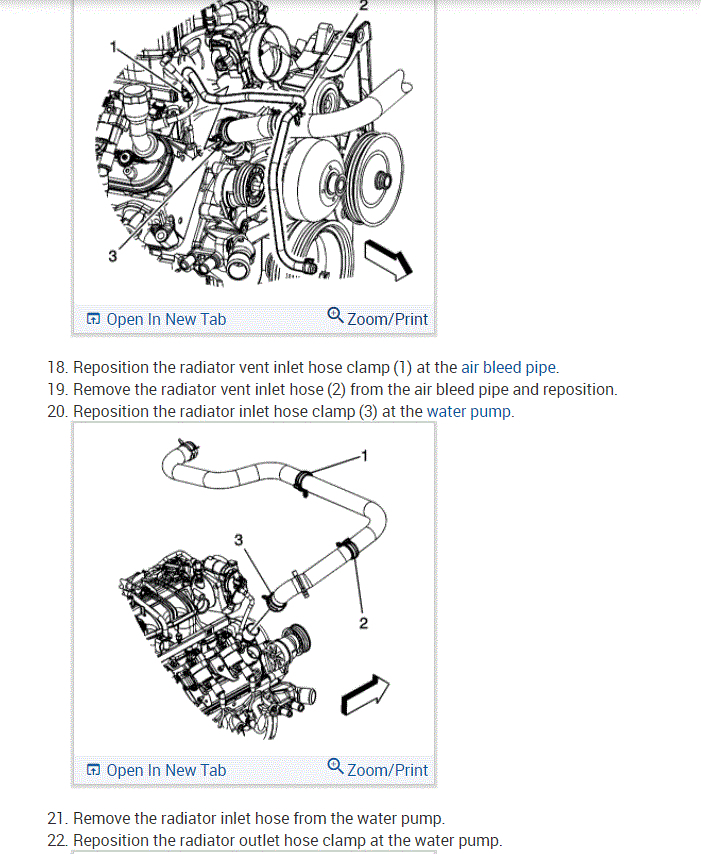
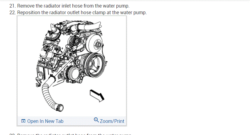
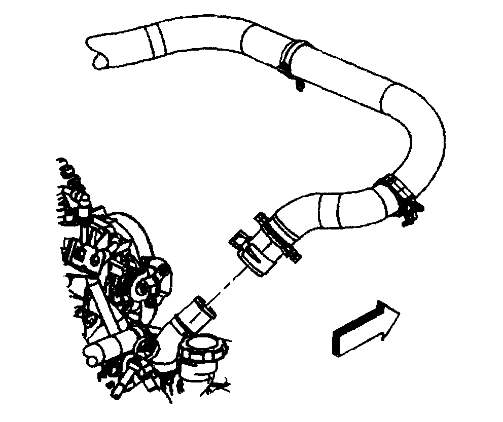
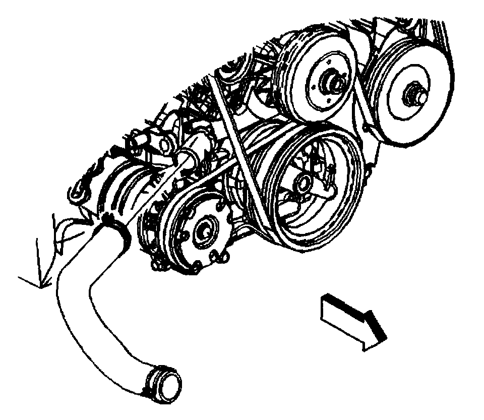
7. Open the hose clamp and remove the radiate inlet hose from the water pump.
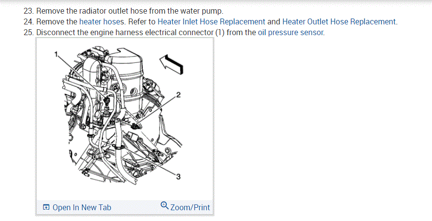
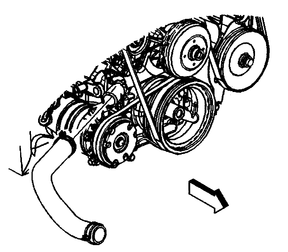
8. Open the hose clamp and remove the radiator outlet hose from the water pump.
9. Remove the heater hoses.
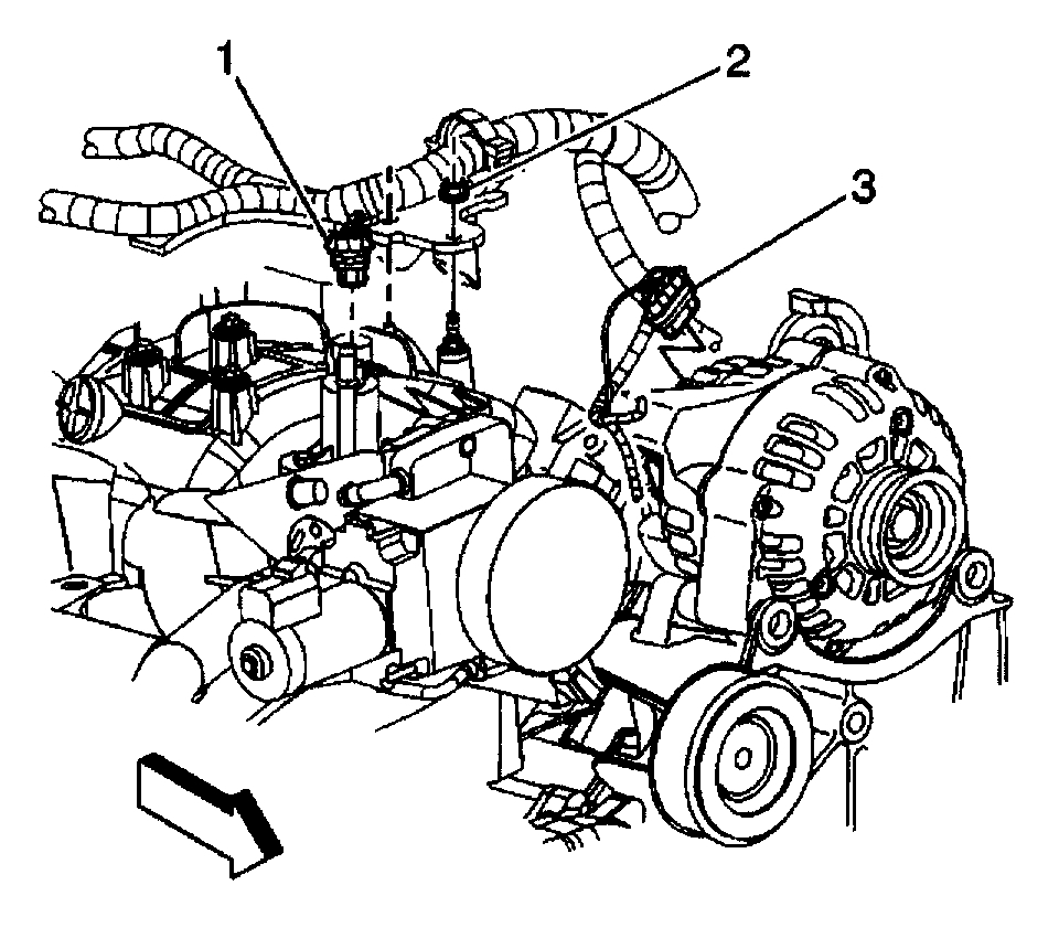
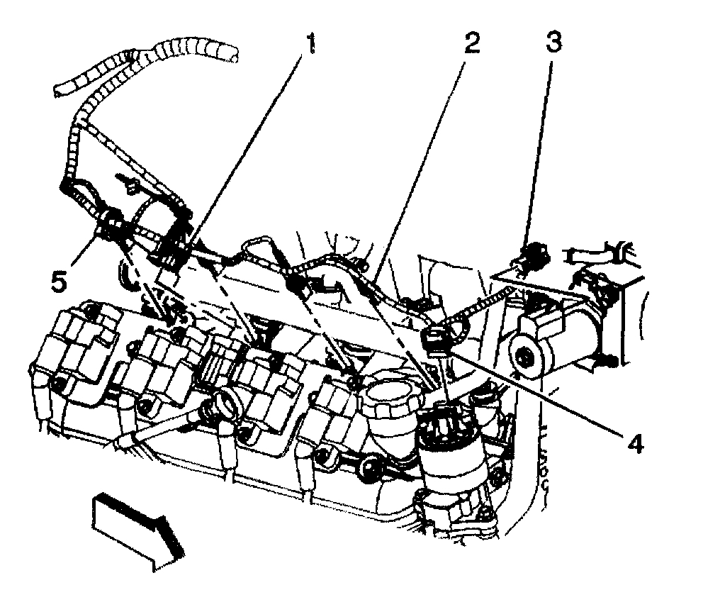
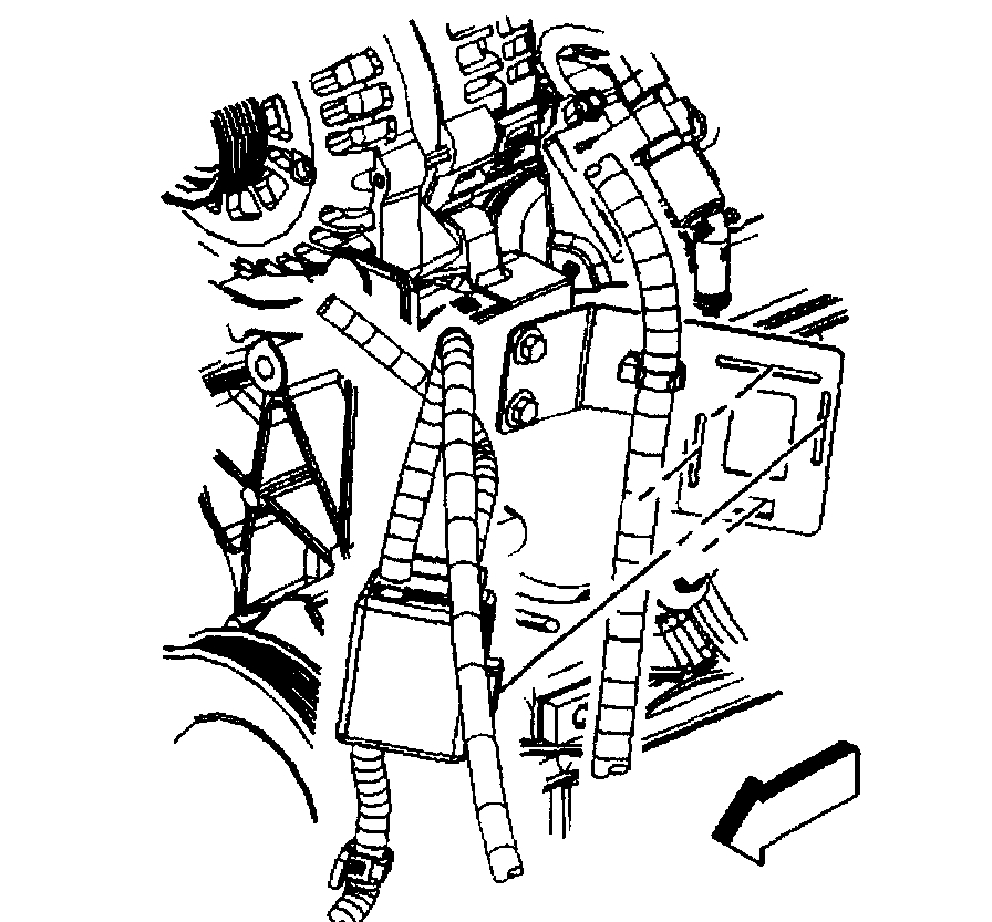
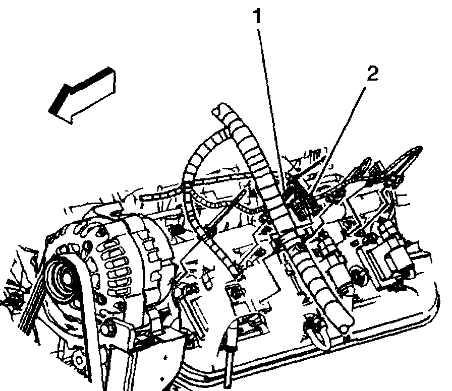
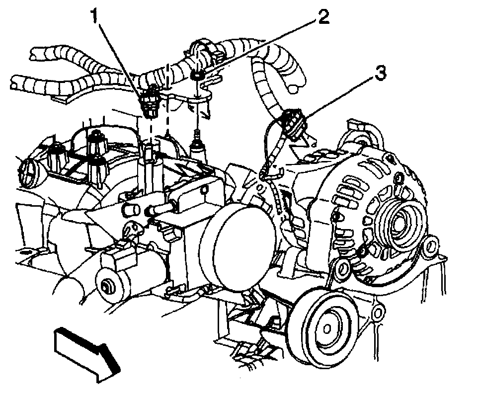
10. Disconnect the following electrical connectors:
- Evaporative Emissions (EVAP) canister purge solenoid (1)
- Generator (3)
11. Remove the harness bracket nut (2) in order to remove the engine harness from the intake manifold.
12. Reposition the vent inlet hose clamp at the throttle body.
13. Remove the radiator vent inlet hose from the throttle body.
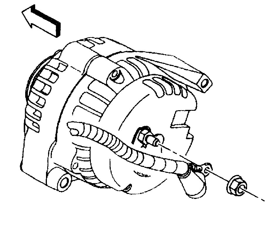
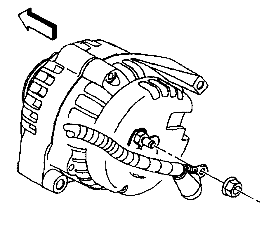
14. Remove the generator cable from the generator, perform the following:
14.1. Slide the boot down revealing the terminal stud.
14.2. Remove the generator cable nut from the terminal stud.
14.3. Remove the generator cable.
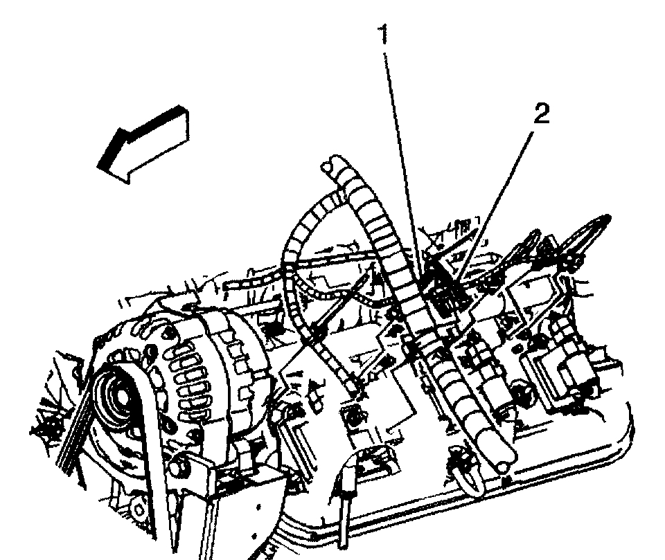
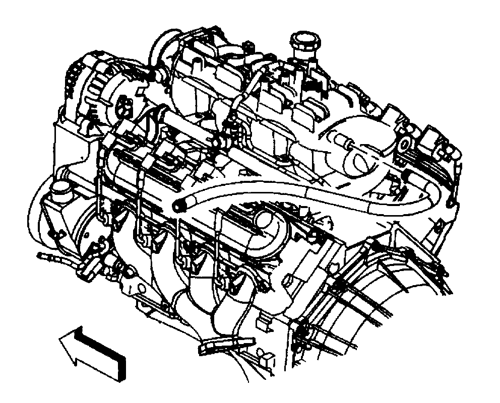
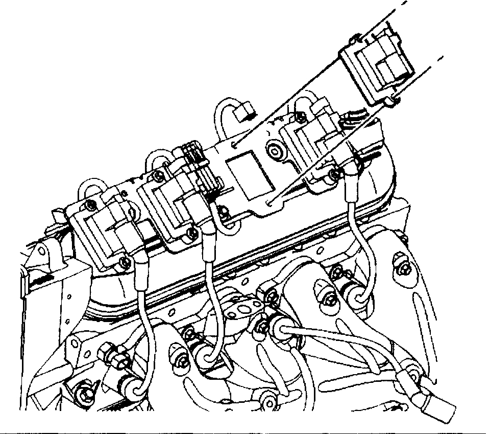
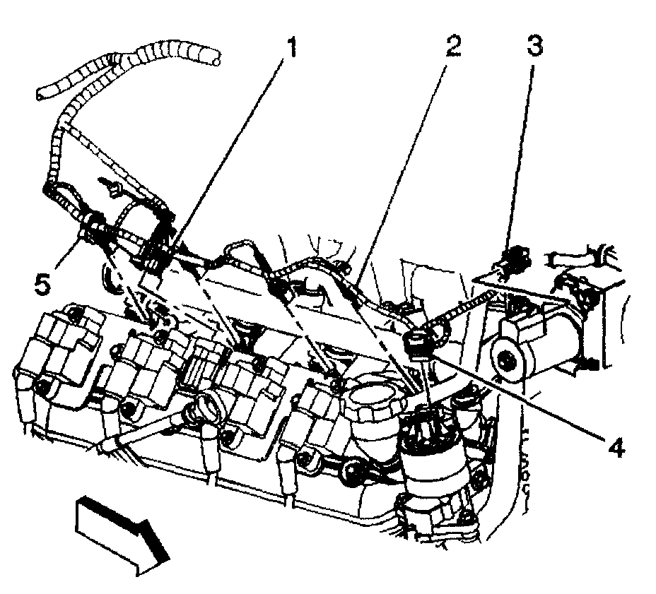
15. Disconnect the main coil harness (2) and fuel injector electrical connectors on the left side.
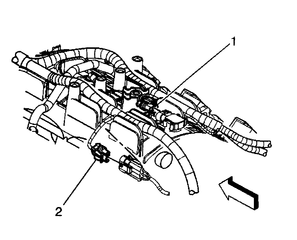
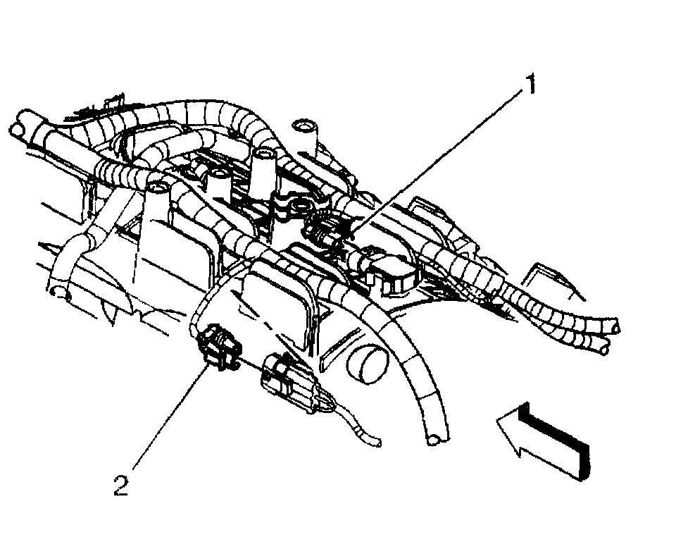
16. Disconnect the following electrical connectors:
- Main coil harness (1)
- Fuel injectors (2)
- Electronic Throttle Control (ETC) (3)
17. Disconnect the Manifold Absolute Pressure (MAP) sensor (1) and knock sensor (2) electrical connectors.
18. Remove the harness ground bolt.
19. Reposition the harness ground and negative battery cable from the block.
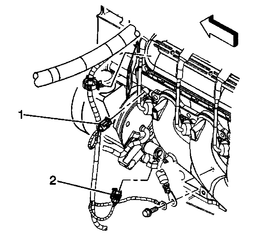
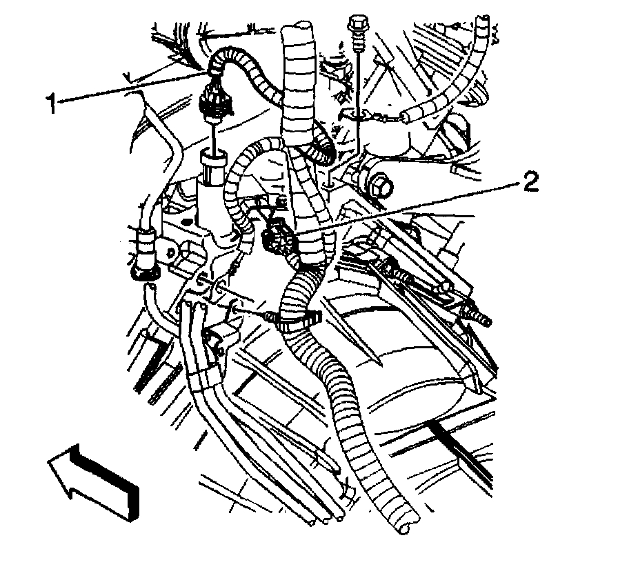
20. Disconnect the following electrical connectors:
- Engine Coolant Temperature (ECT) sensor (1)
- Electronic variable orifice switch (2)
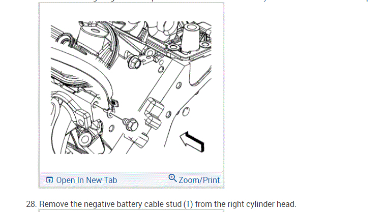
21. Remove the harness ground bolt at the right rear of the engine block.
22. Reposition the harness ground, and auxiliary negative battery cable, if equipped, from the block.
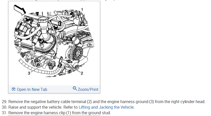
23. Remove the harness ground bolt at the left rear of the engine block.
24. Reposition the harness ground, and engine ground strap from the block.
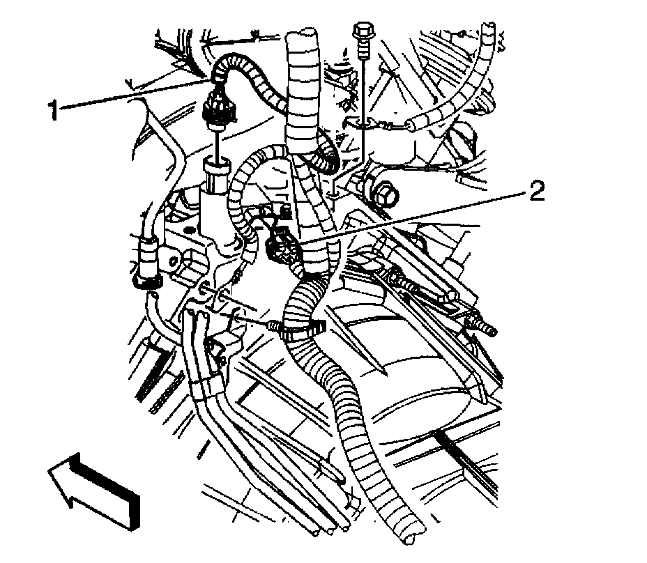
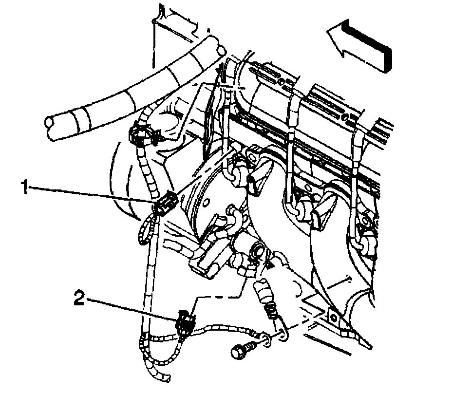
25. Disconnect the following electrical connectors:
- Oil pressure sensor (1)
- Camshaft Position (CMP) sensor (2)
26. Unclip all of the engine harness clips from the engine.
27. Remove the battery cable junction block from the junction block bracket.
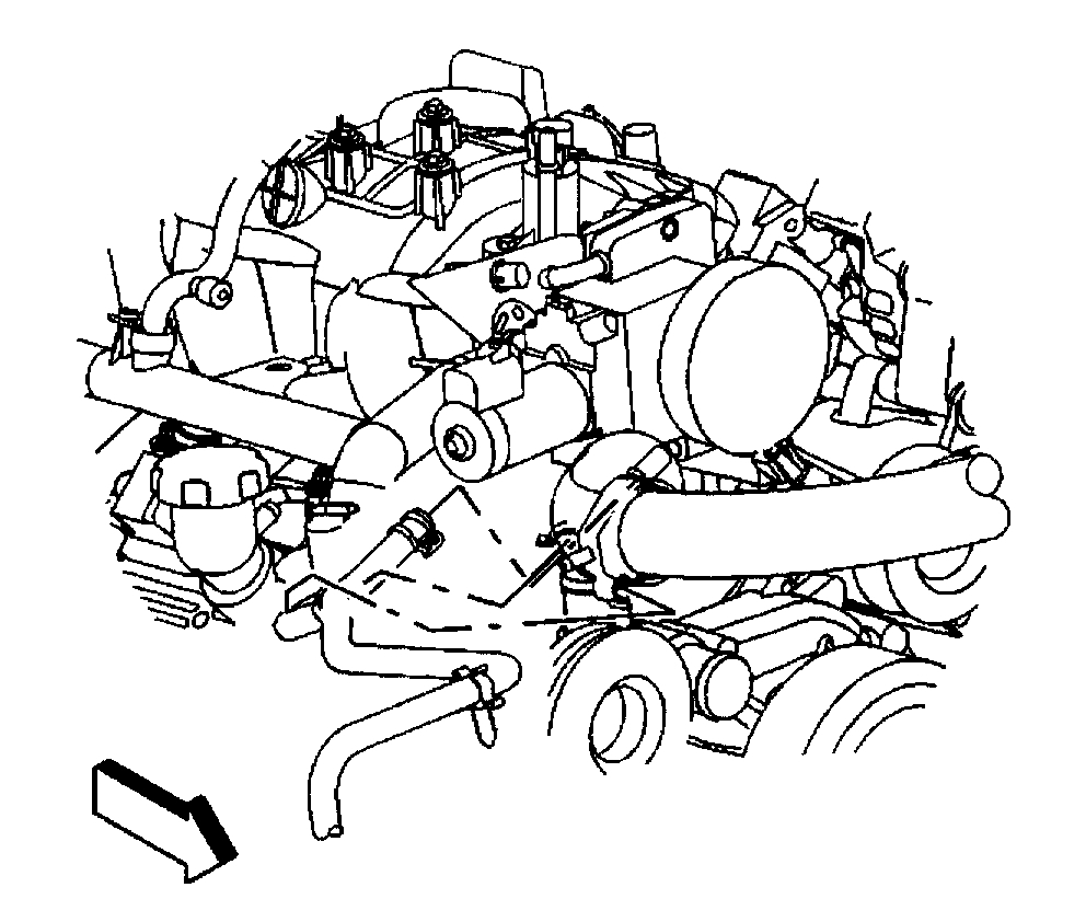
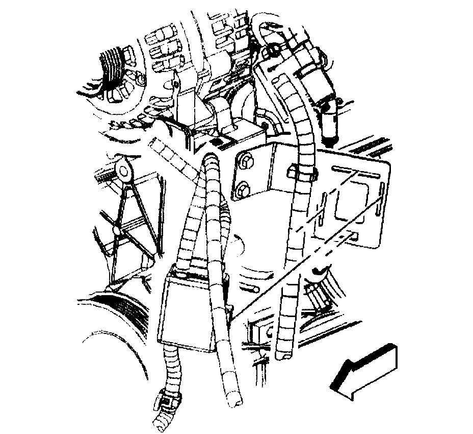
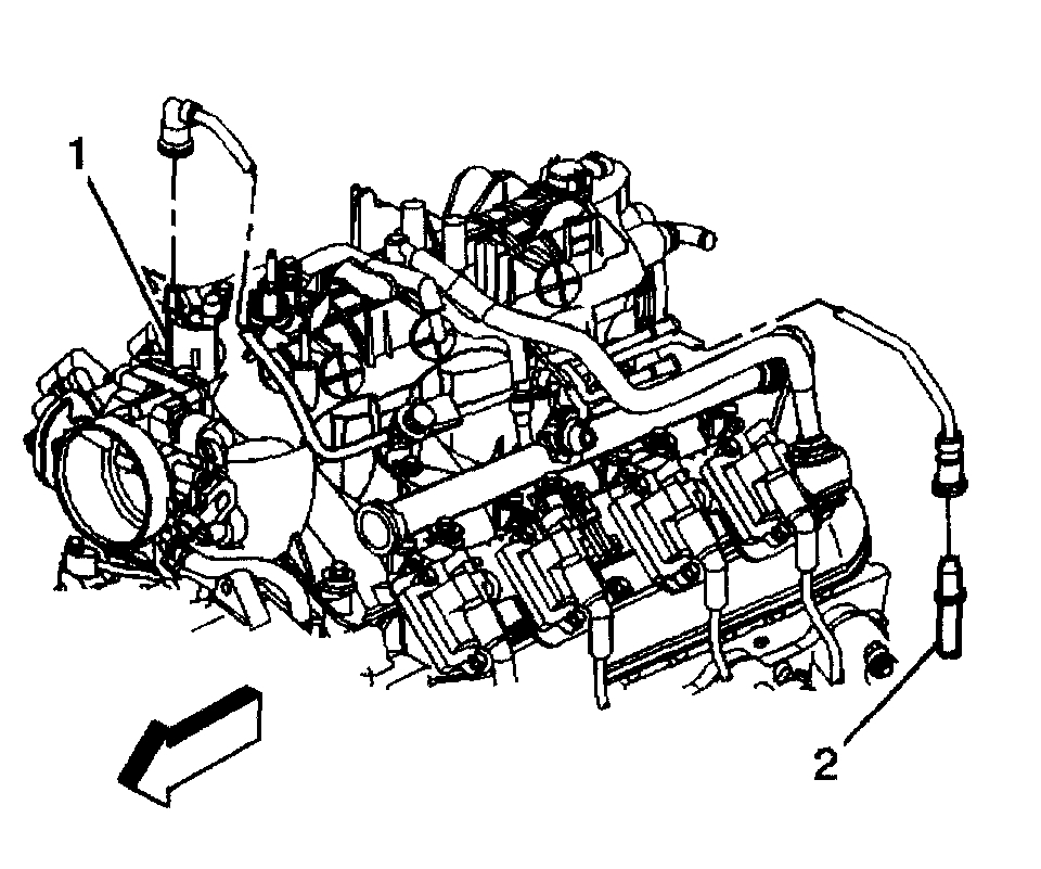
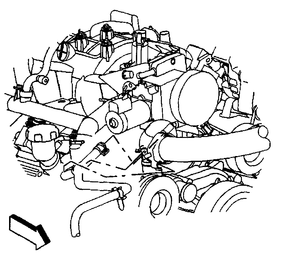
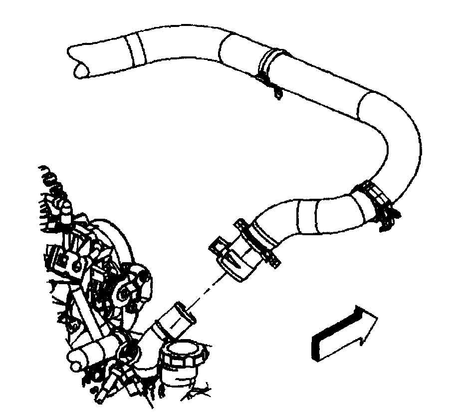
28. Remove the EVAP purge solenoid vent tube; perform the following:
- Remove the EVAP tube end from the solenoid (1).
- Remove the EVAP tube end from the vapor Pipe (2).
29. Disconnect the fuel pipes.
30. Raise the vehicle.
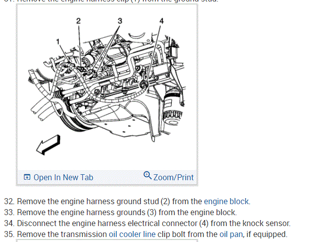
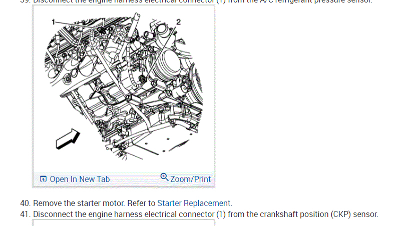
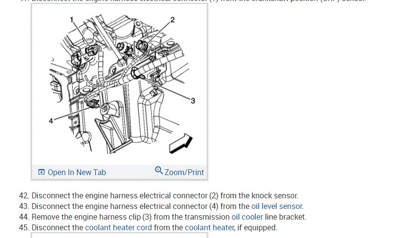
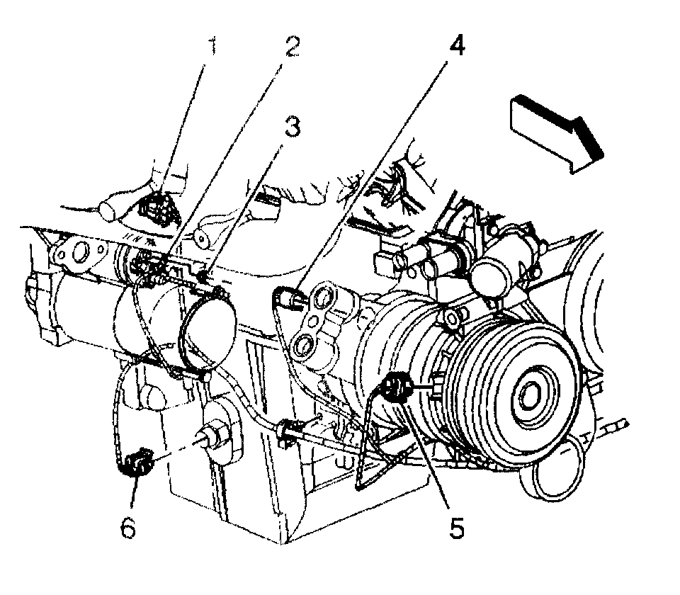
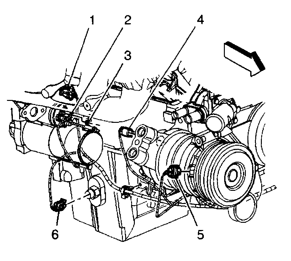
31. Disconnect the following electrical connectors:
- Crankshaft Position (CKP) sensor (1)
- Engine oil sensor (6)
- Coolant heater, if equipped.
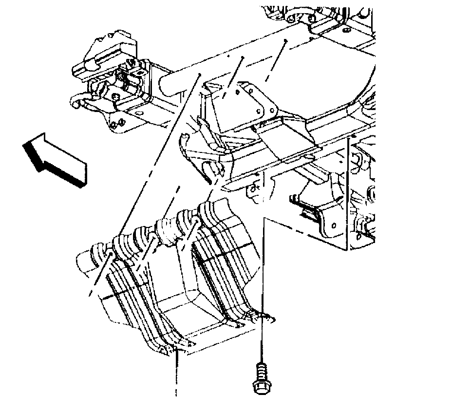
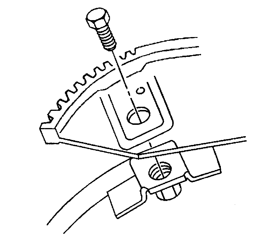
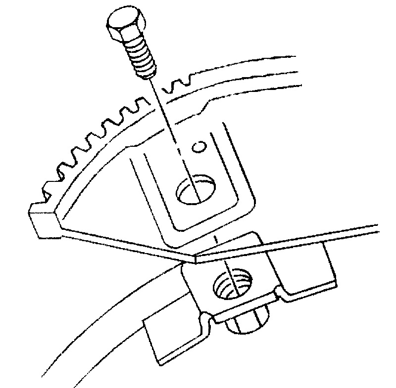
32. Remove the battery cable channel bolt.
33. Slide the channel pin out of the oil pan tab.
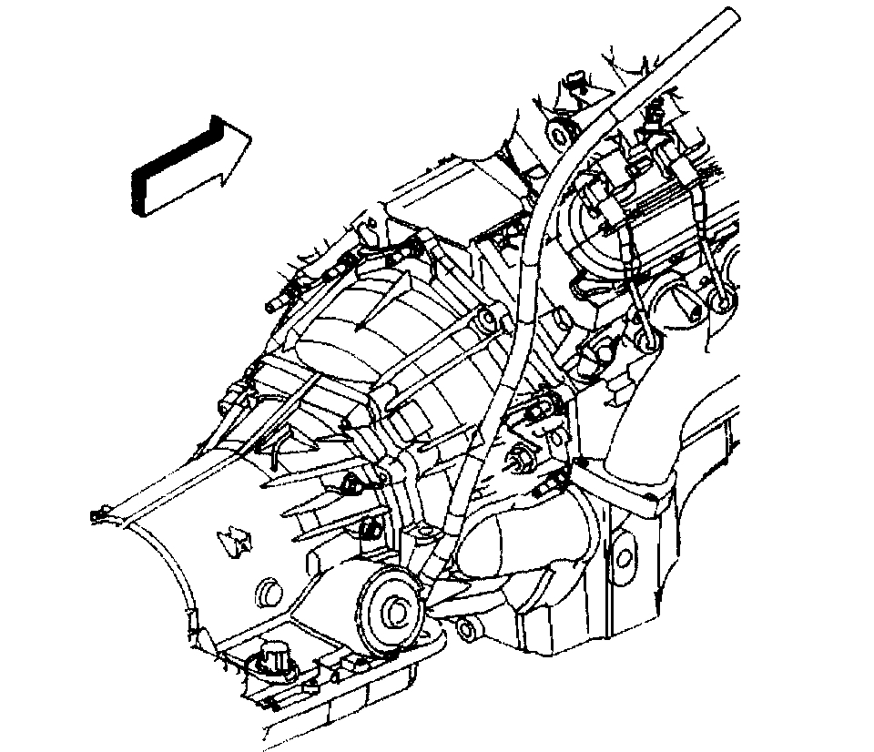
34. Gather all branches of the engine wiring harness and reposition off to the side.
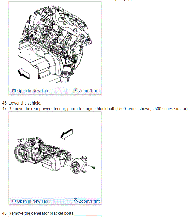
35. Lower the vehicle.
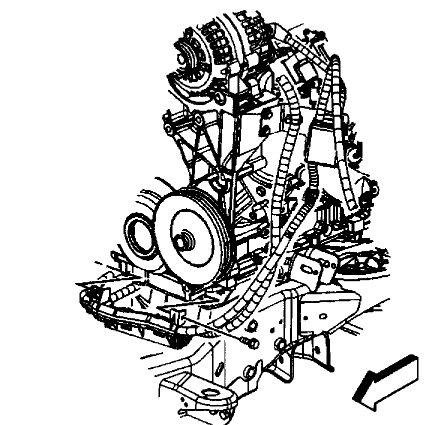
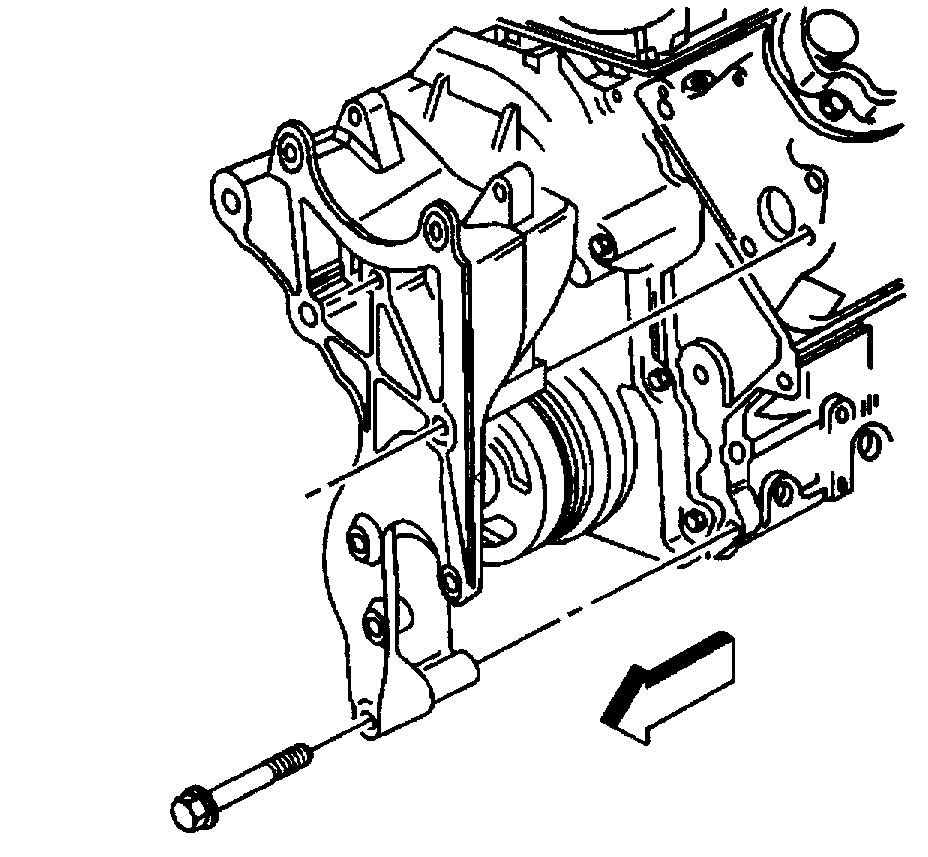
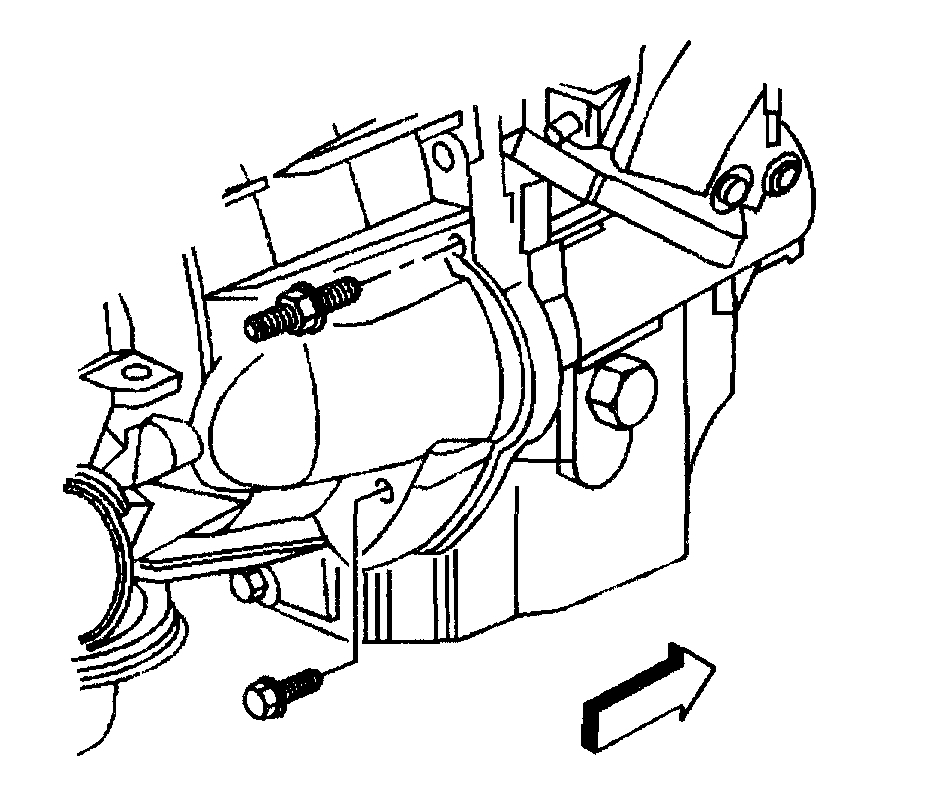
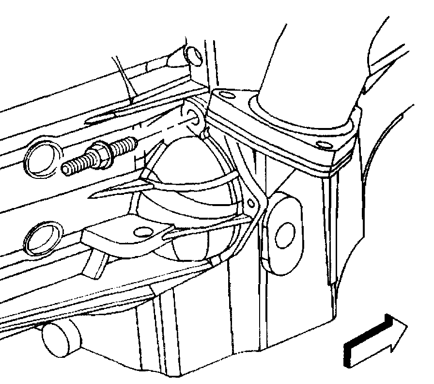
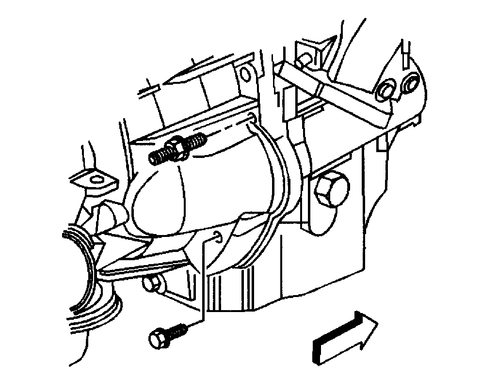
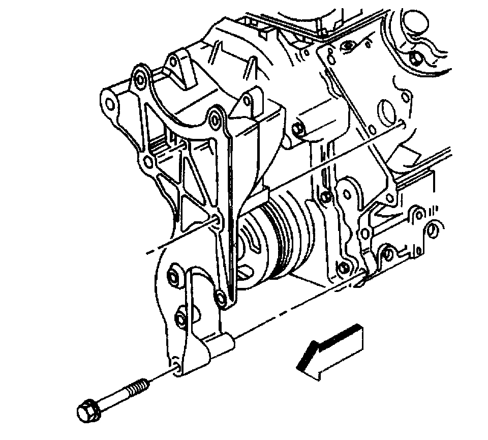
36. Remove the rear power steering to engine block bolt.
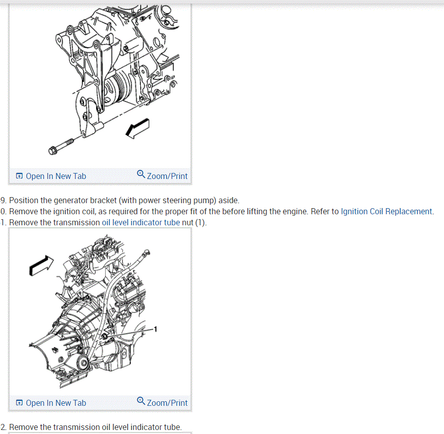
37. Remove the generator bracket bolts.
38. Position the bracket aside.
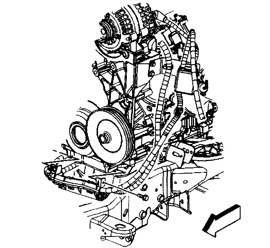
39. Remove the vacuum brake booster hose.
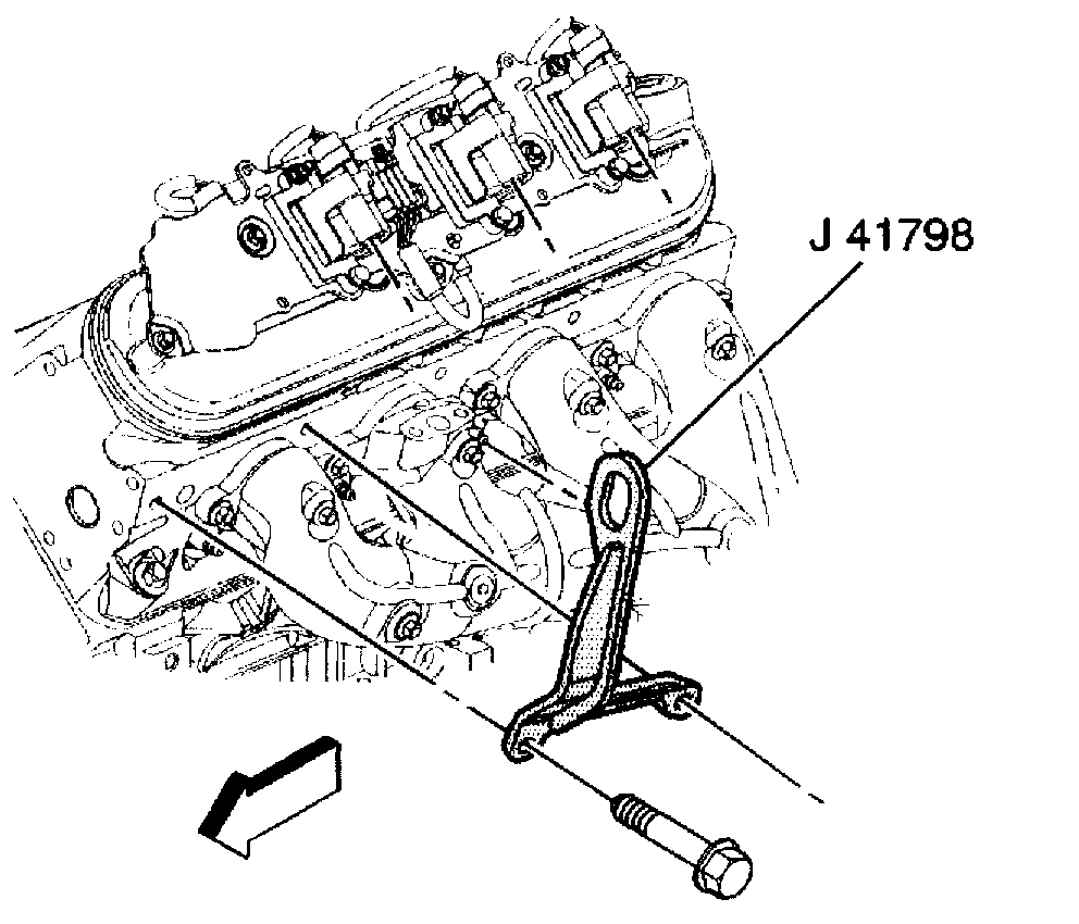
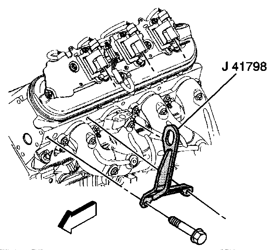
40. Remove the ignition coil(s) (as required) for the proper fit of the J41798 before lifting the engine.
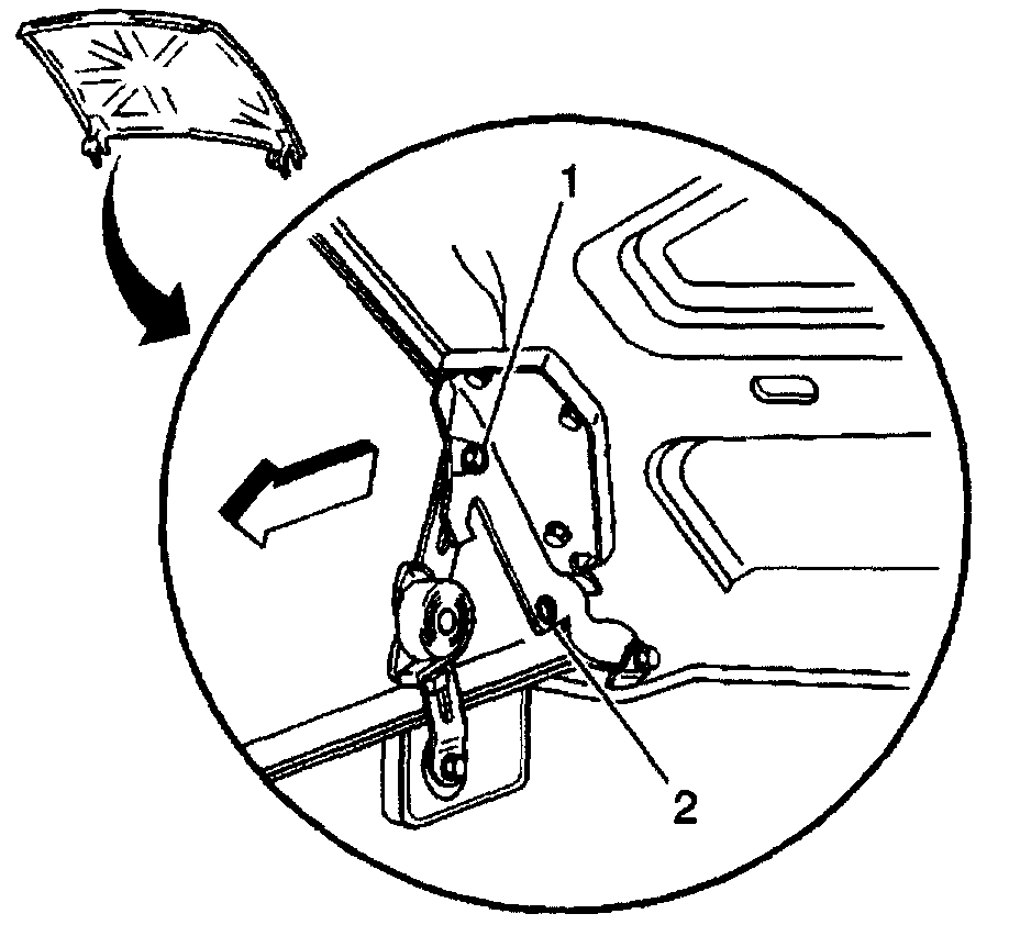
Notice:Refer to Fastener Notice in Service Precautions.
See: Engine, Cooling and Exhaust > Vehicle Damage Warnings > Fastener Notice
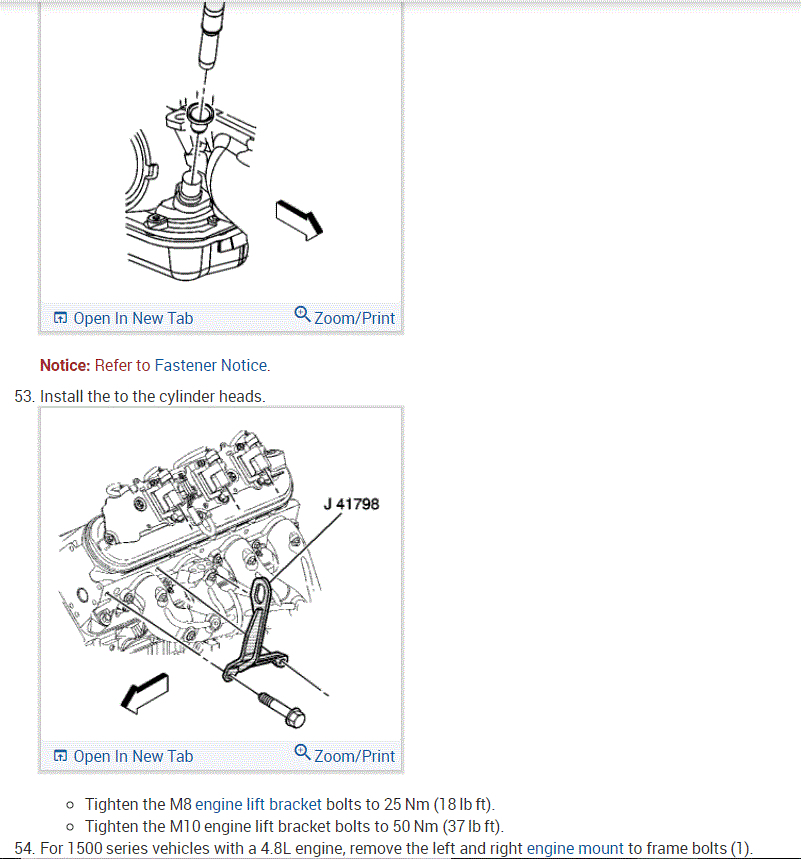
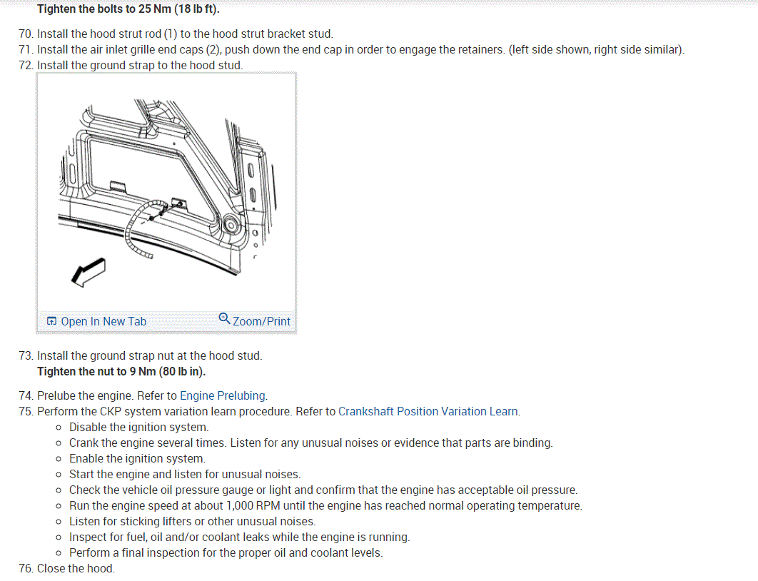
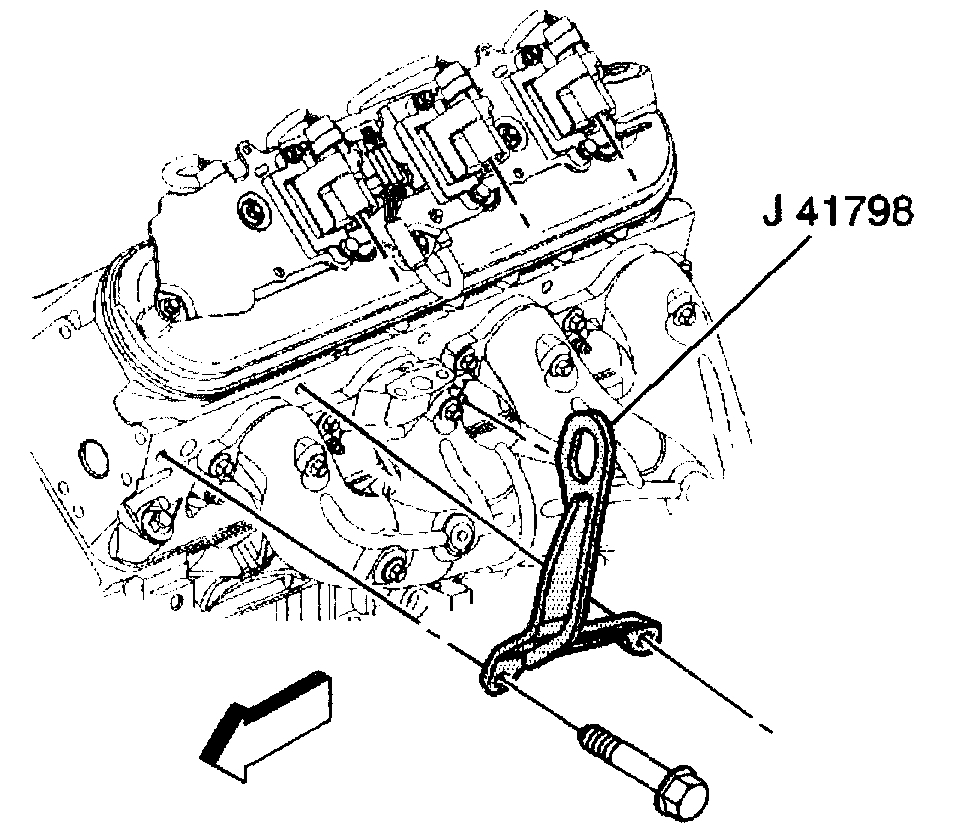
41. Install the J41798 to the cylinder heads
- Tighten the M8 bolts to 25 Nm (18 ft. Lbs.).
- Tighten the M10 bolts to 50 Nm (37 ft. Lbs.).
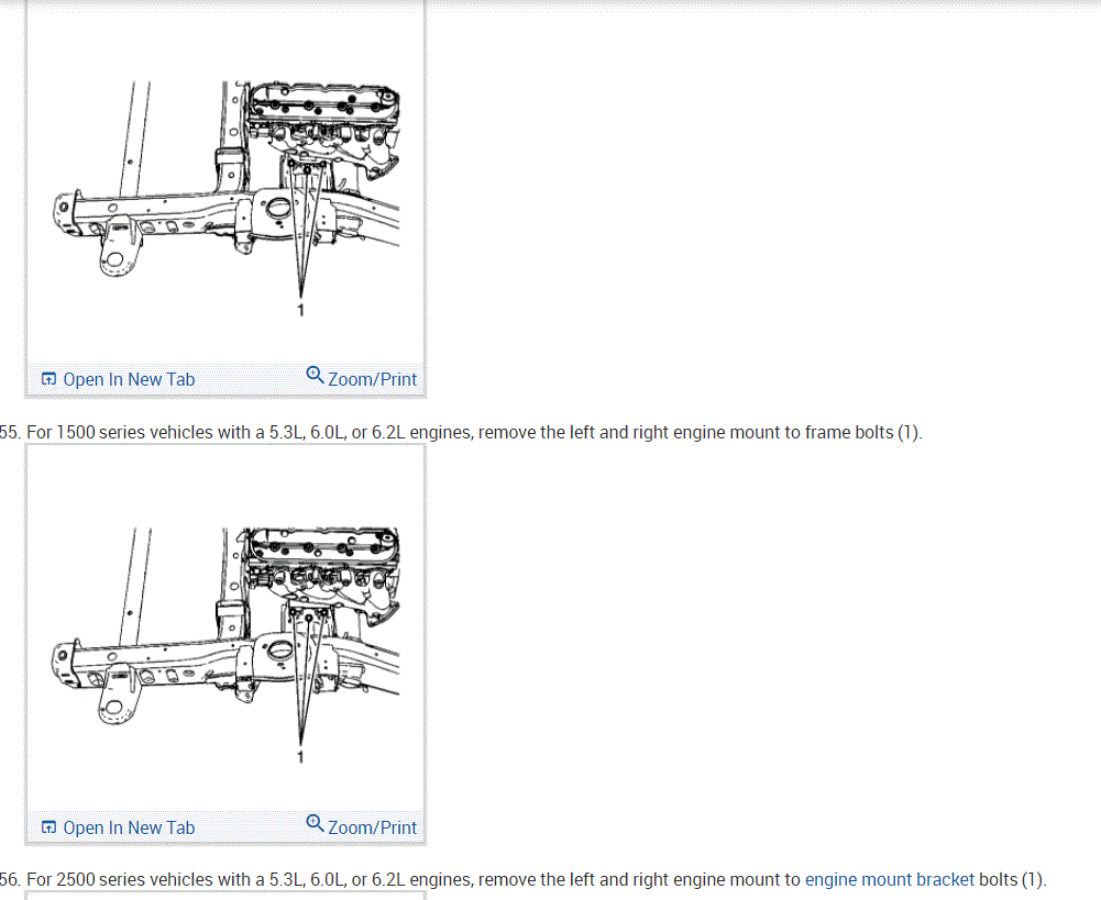
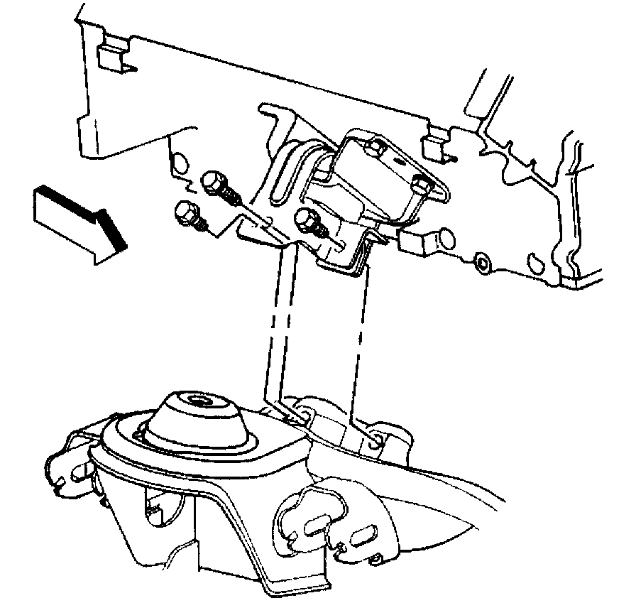
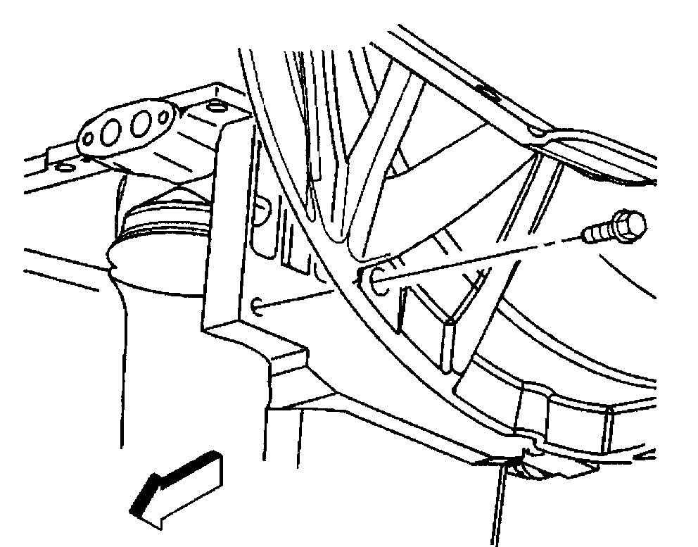
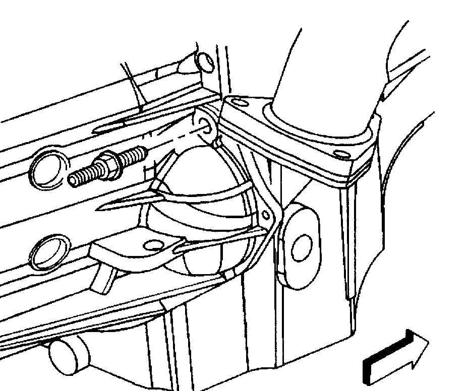
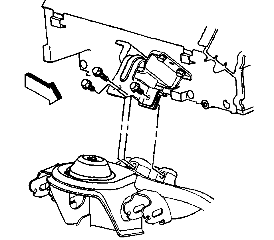
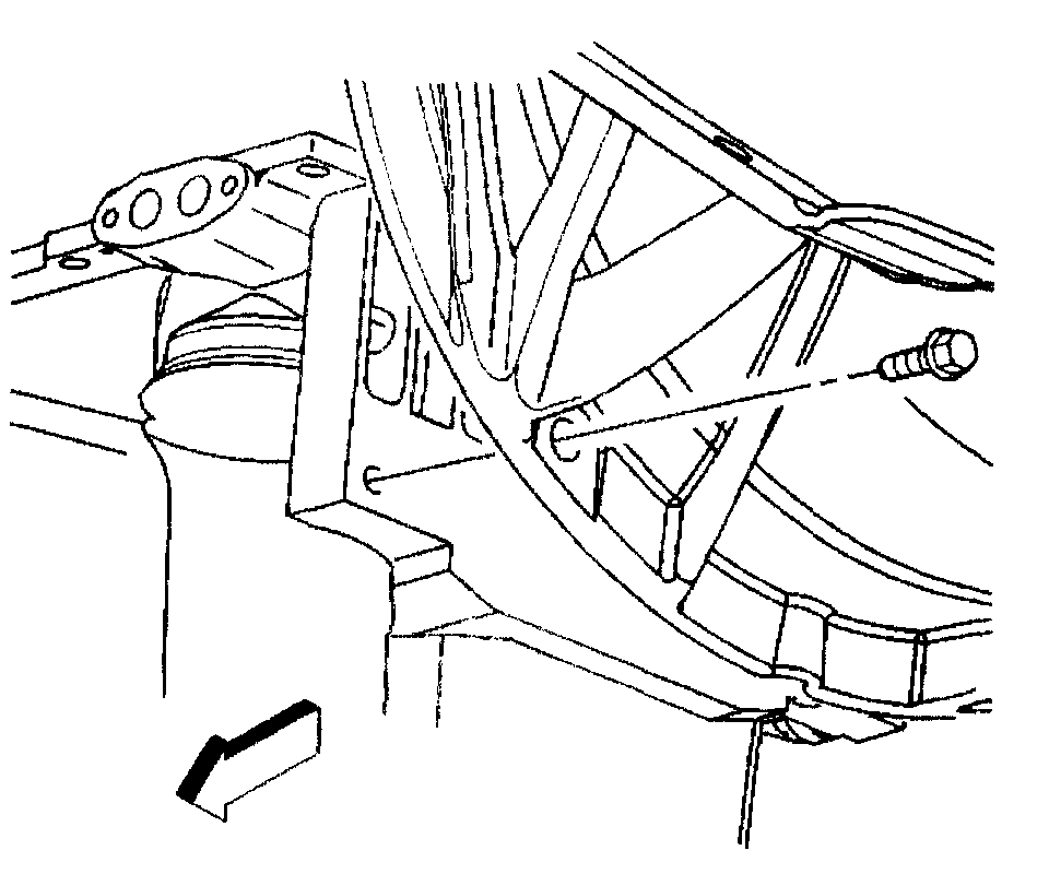
42. Remove the left and right engine mount to engine mount bracket bolts.
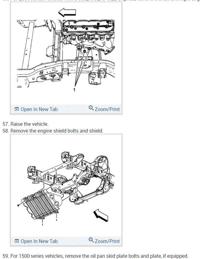
43. Raise the vehicle.
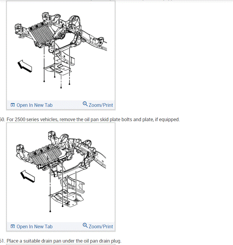
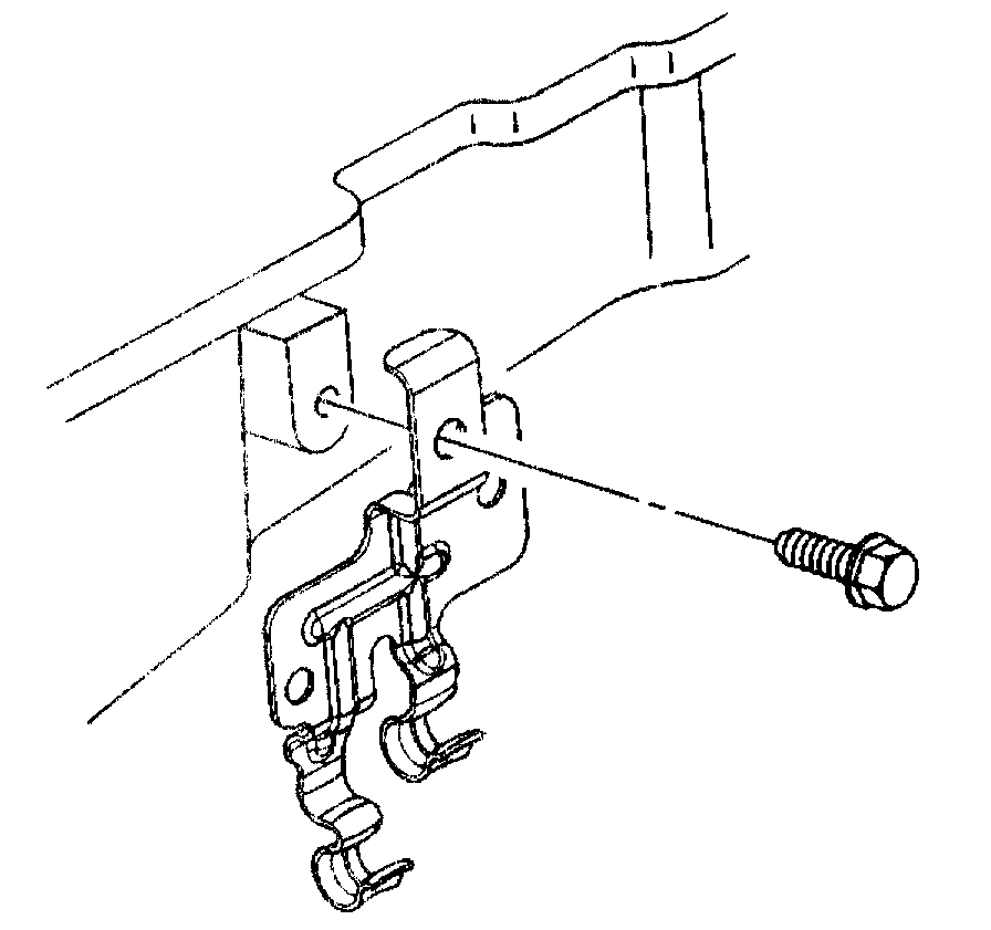
44. Remove the engine sight shield bolts and shield.
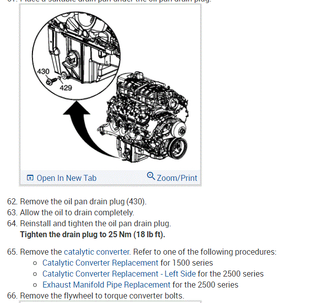
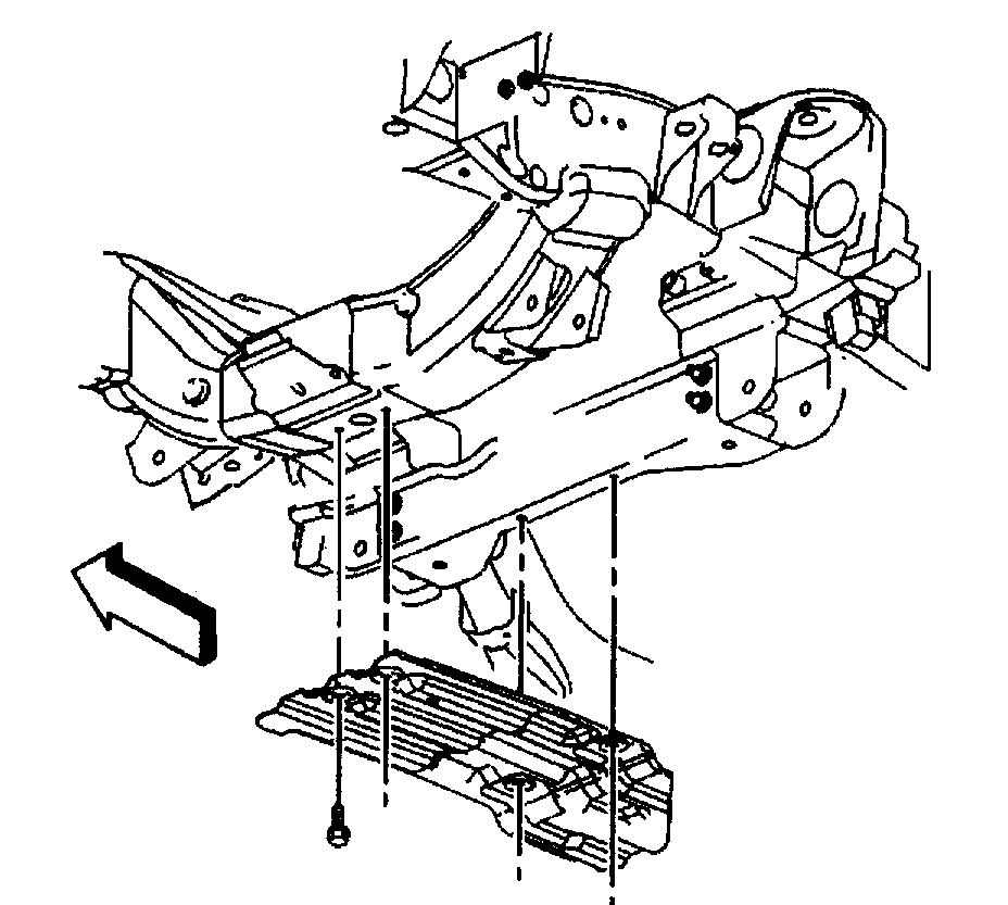
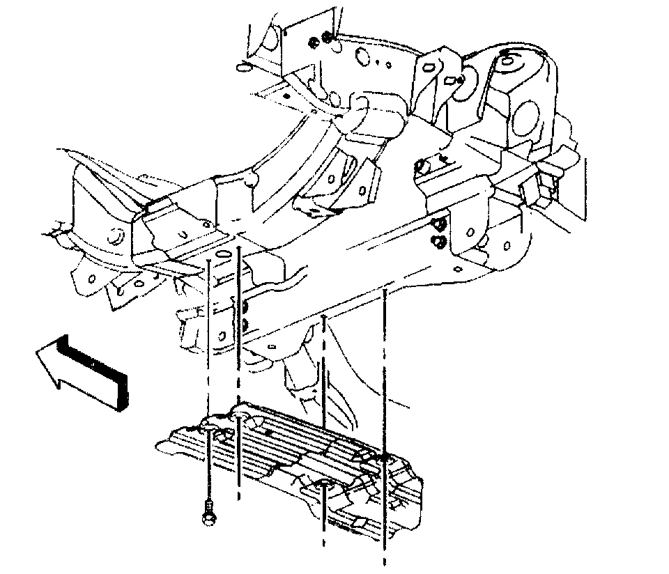
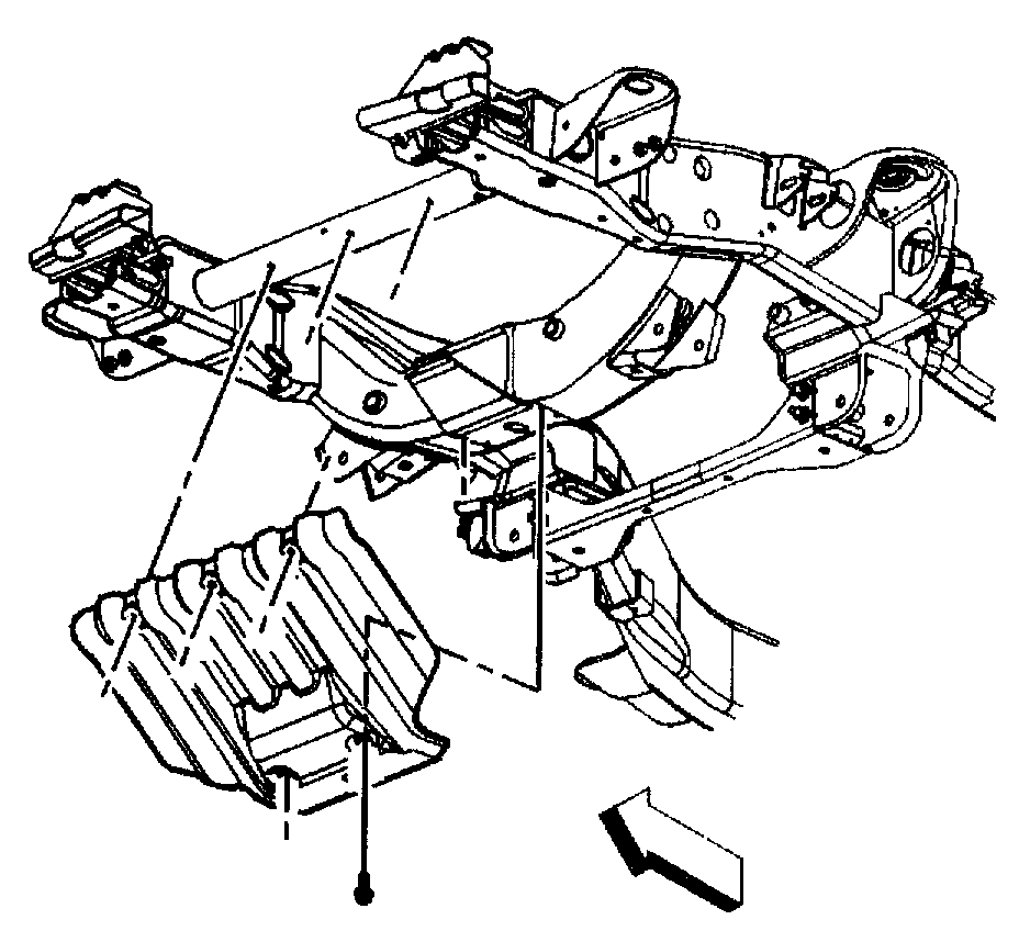
45. Remove the oil pan skid plate bolts and plate, if equipped.
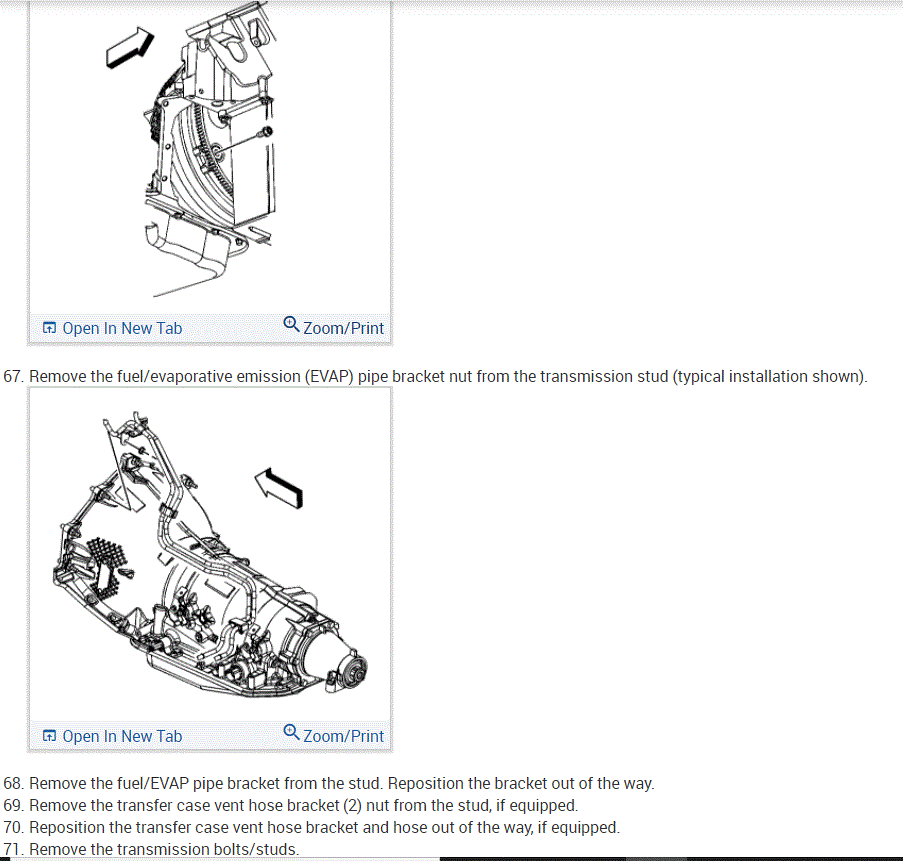
46. Drain the engine oil.
47. Remove the starter motor.
48. Remove the catalytic converter.
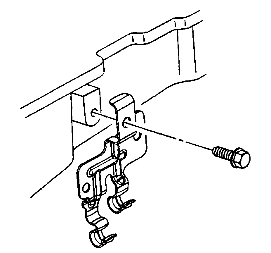
49. Remove the positive battery cable clip bolt and clip.
50. Remove the torque converter bolts, if equipped.
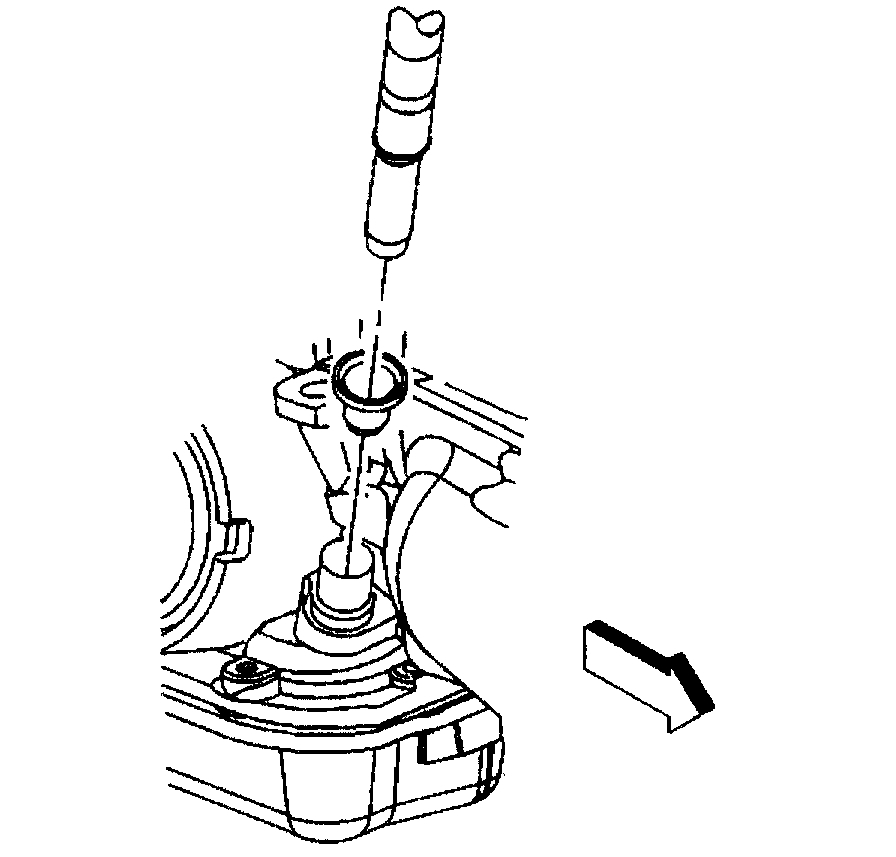
51. Remove the transmission oil level indicator tube nut, if equipped.
52. Remove the transmission oil level indicator tube, if equipped.
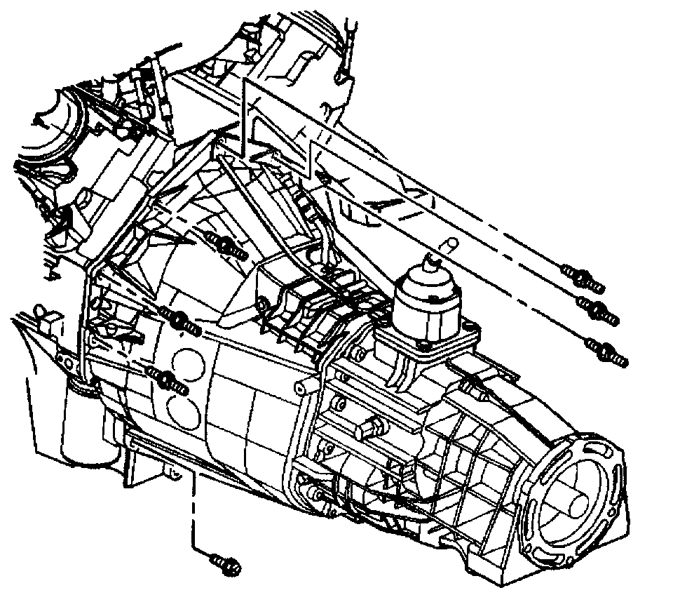
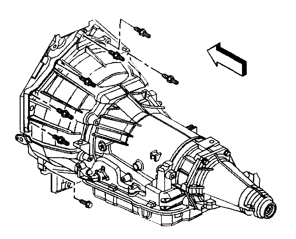
53. If equipped with a 4L60E transmission, remove the transmission bolt and stud on the right side.
54. If equipped with a 4L80E transmission, remove the transmission converter cover bolts.
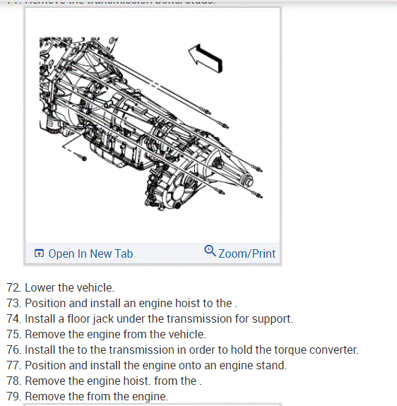
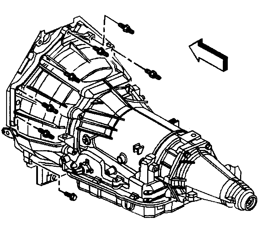
55. Remove the automatic transmission bolt/studs, if equipped.
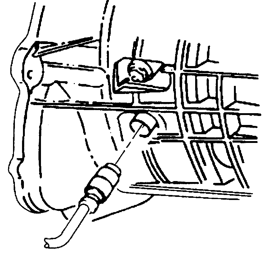
56. Separate the engine from the automatic transmission, if equipped. Install the J21366 to the transmission in order to hold the torque converter.
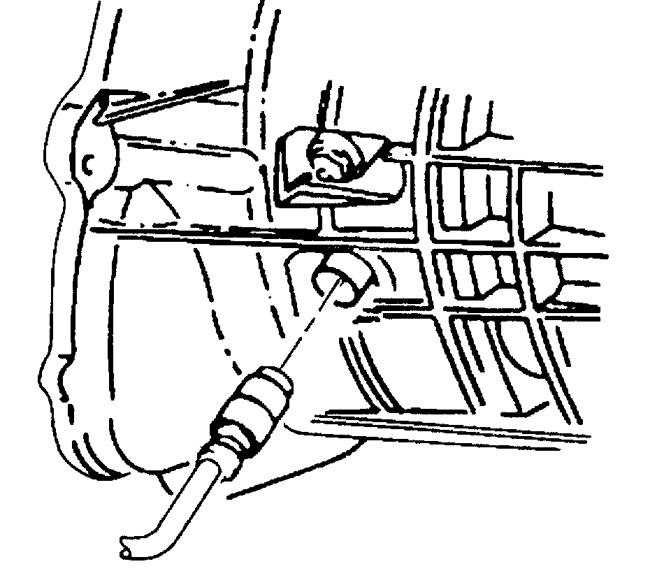
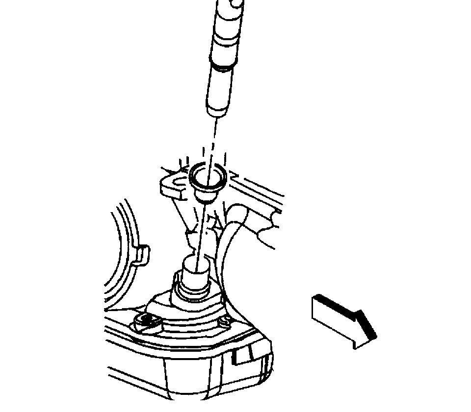
57. Using J42371 remove the clutch line form the concentric slave cylinder.
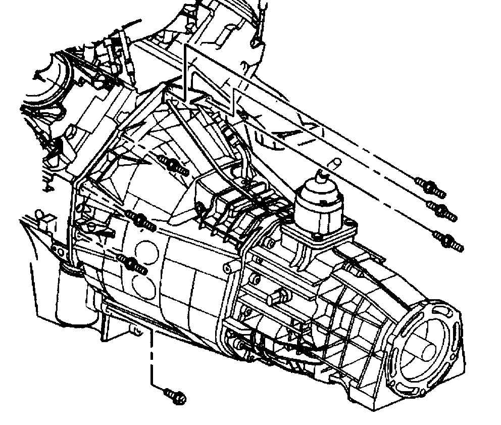
58. Remove the manual transmission stud on the right side of the transmission, if equipped.
59. Remove the manual transmission bolt/studs, if equipped.
60. Separate the manual transmission from the engine, if equipped.
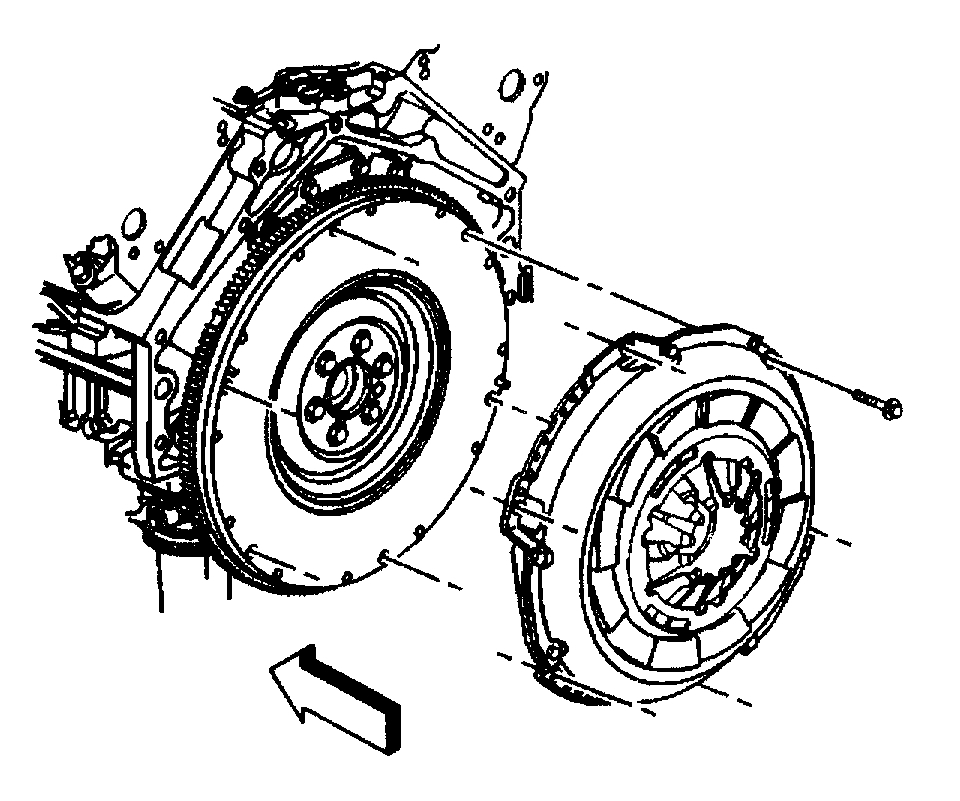
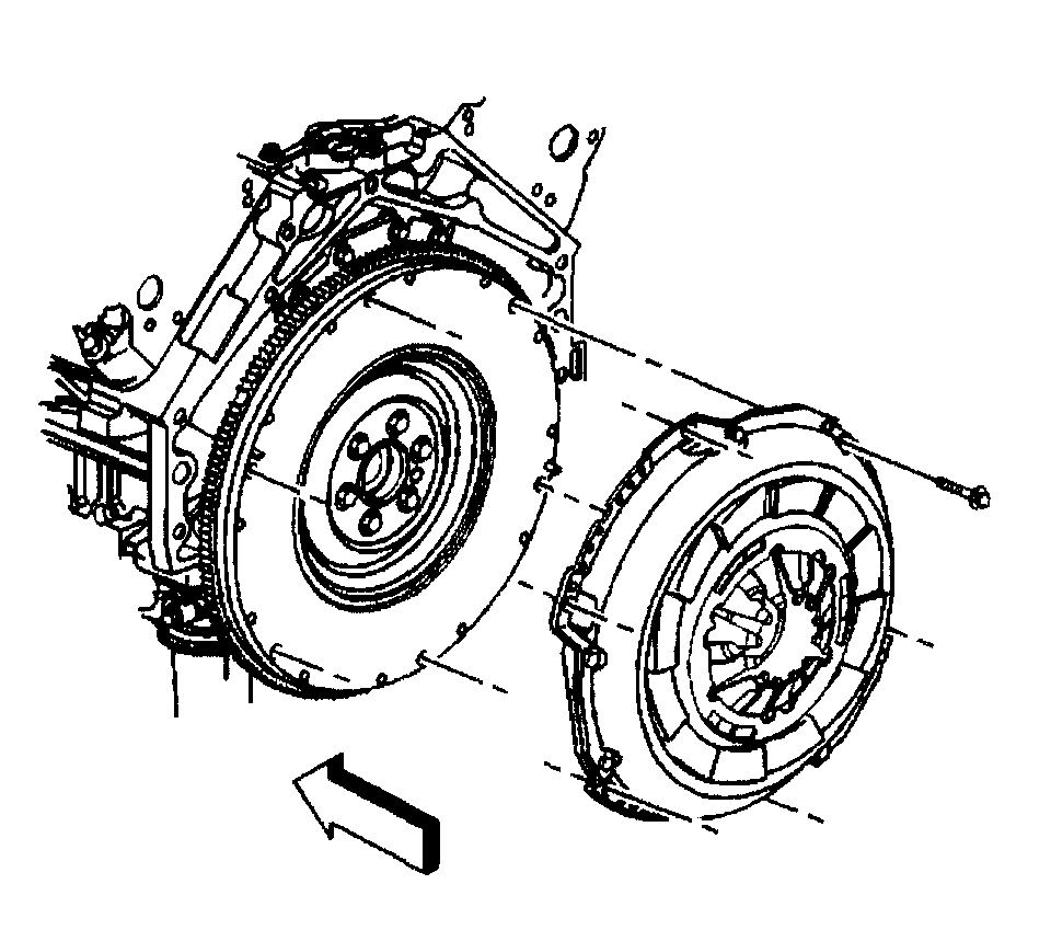
61. Mark the flywheel and a clutch pressure plate lug for installation alignment.
62. Remove the clutch pressure plate bolts, if equipped.
63. Remove the clutch pressure plate and disc, if equipped.
64. Lower the vehicle.
65. Install an engine hoist to the J41798.
66. Install a floor jack under the transmission for support.
Notice:Use care while moving the engine assembly in order to avoid breaking the MAP sensor locating tabs. Broken MAP sensor tabs may result in decreased engine performance.
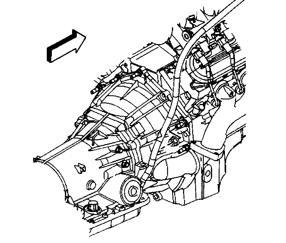
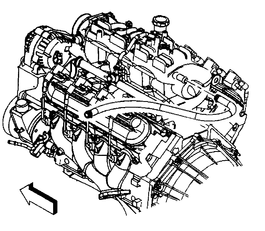
67. Remove the engine.
68. Install the engine to an engine stand.
69. Remove the engine hoist.
70. Remove the J41798 from the engine.
ENGINE INSTALLATION
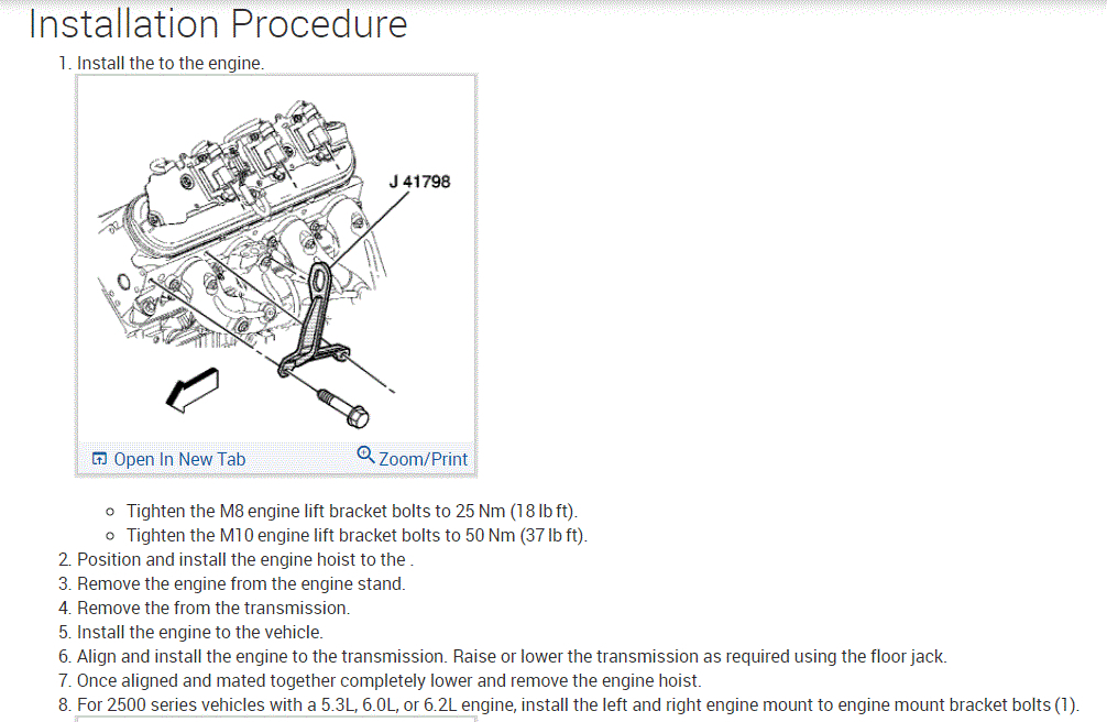
Installation Procedure
Notice:Refer to Fastener Notice in Service Precautions.
See: Engine, Cooling and Exhaust > Vehicle Damage Warnings > Fastener Notice
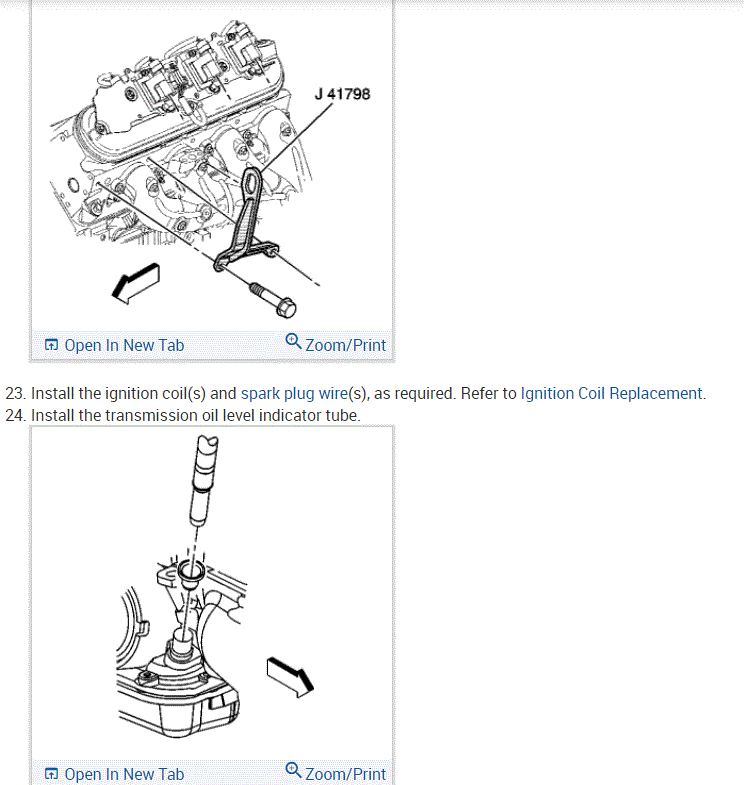
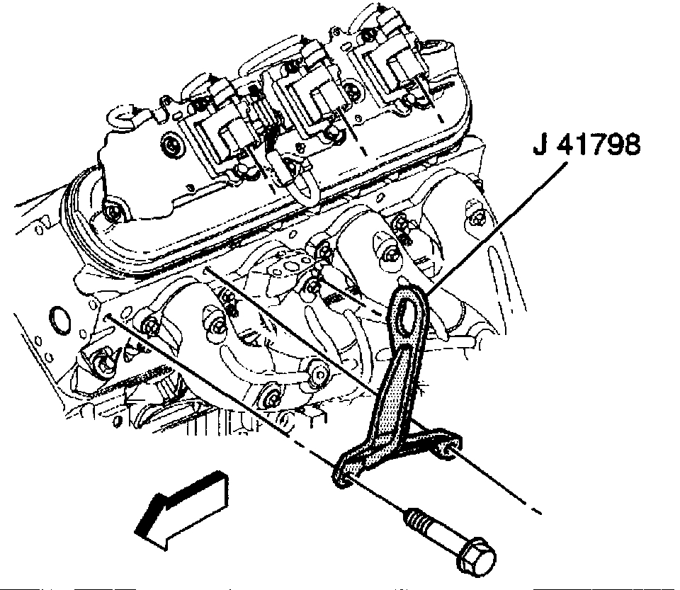
1. Install the J41798 to the engine. Tighten
- Tighten the M8 bolts to 25 Nm (18 ft. Lbs.).
- Tighten the M10 bolts to 50 Nm (37 ft. Lbs.).
2. Install an engine hoist to the J41798.
3. Remove the engine from the engine stand.
4. Install the engine to the vehicle.
5. Align the engine and transmission.
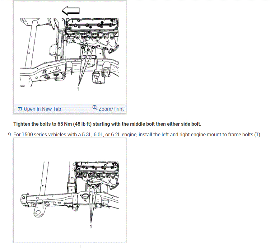
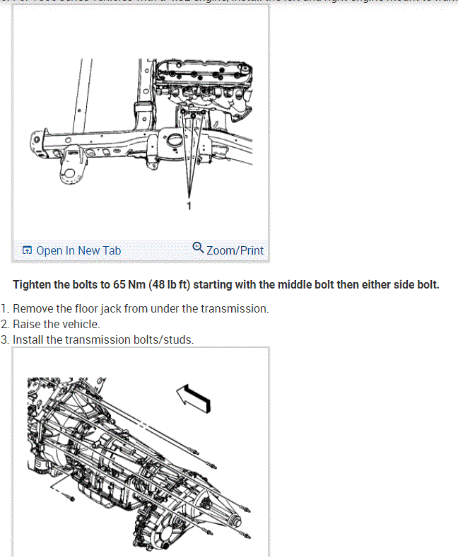
6. Install the left and right engine mount to engine mount bracket bolts.
Tighten the bolts to 65 Nm (48 ft. Lbs.).
7. Install the upper transmission bolts until snug.
8. Remove the floor jack from under the transmission.
9. Remove the engine hoist.
10. Remove the J41798 from the engine.
11. Install the ignition coil(s) and the spark plug wire(s).
12. Raise the vehicle.
13. Install the disc and clutch pressure plate and bolts until snug, if equipped.
14. Using J5824-01, align the clutch disc splices with the pilot bearing.
15. Align the marks made during removal.
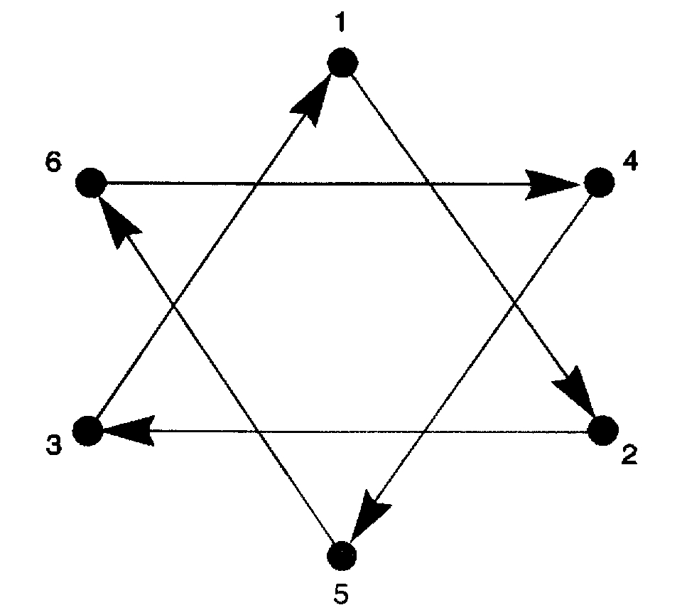
16. Tighten the clutch pressure plate bolts in the sequence shown, evenly over 3 increments with the fourth increment to the final specification.
Tighten the bolts to 70 Nm (52 ft. Lbs.).
17. Install the clutch line to the concentric slave cylinder.
18. Install the manual transmission bolt/studs, if equipped.
19. Install the manual transmission stud on the right side of the transmission, if equipped.
Tighten the bolt/studs to 50 Nm (37 ft. Lbs.).
20. Remove the J21366 from the transmission.
21. Install the automatic transmission, if equipped.
22. If equipped with a 4L80E transmission, install the transmission converter cover bolts.
23. If equipped with a 4L60E transmission, install the transmission bolt and stud on the right side.
Tighten the bolts/studs to 50 Nm (37 ft. Lbs.).
24. Install the automatic transmission oil level indicator tube, if equipped.
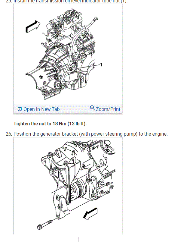
25. Install the automatic transmission oil level indicator tube nut, if equipped.
Tighten to nut to 18 Nm (13 ft. Lbs.).
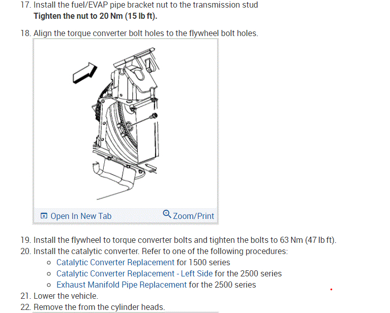
26. Install the torque converter bolts, if equipped.
- If equipped with a 4L60E, tighten the bolts to 63 Nm(47 ft. Lbs.)
- If equipped with a 4L80E, tighten the bolts to 60 Nm (44 ft. Lbs.).
27. Install the positive cable clip and bolt.
Tighten the bolt to 9 Nm (80 inch lbs.).
28. Install the catalytic converter.
29. Install the starter motor.
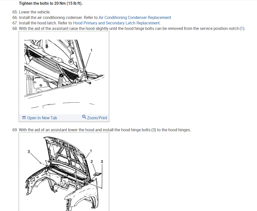
30. Install the oil pan skid plate and bolts, if equipped.
Tighten the bolts to 20 Nm (15 ft. Lbs.).
31. Install the engine shield and bolts.
Tighten the bolts to 20 Nm (15 ft. Lbs.).
32. Lower the vehicle.
33. Install the vacuum brake booster hose.
34. Position the generator bracket to the front of the engine.
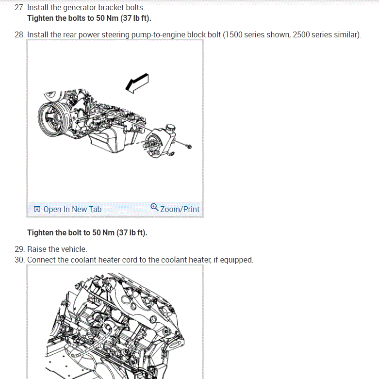
35. Install the generator bracket bolts until snug.
36. Install the rear power steering pump to engine block bolt, until snug.
Tighten the bolts to 50 Nm (37 ft. Lbs.).
37. Route the engine wiring harness to the lower engine area.
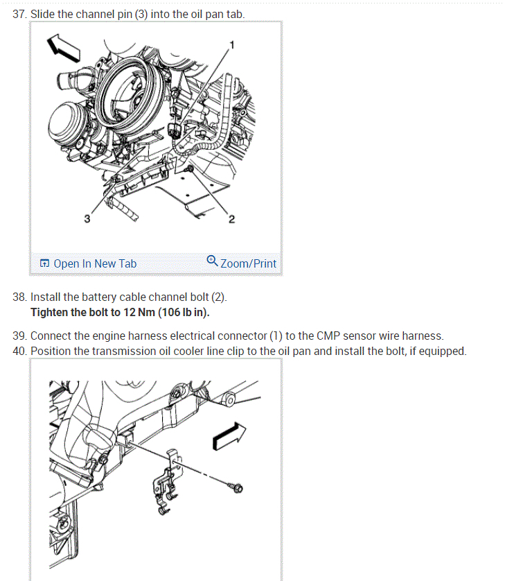
38. Raise the vehicle.
39. Slide the channel pin into the oil pan tab.
40. Install the battery cable channel bolt.
Tighten the bolt to 12 Nm (106 inch lbs.).
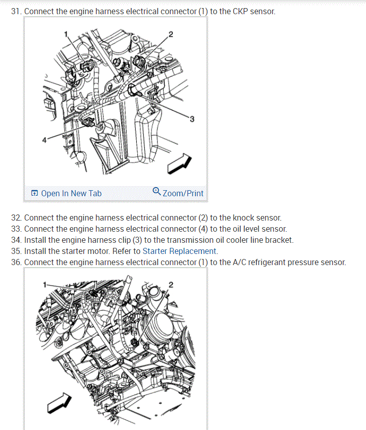
41. Connect the following electrical connectors:
- CKP sensor (1)
- Engine oil level sensor (6)
- Coolant heater, if equipped.
42. Lower the vehicle.
43. Connect the fuel pipes.
44. Install the EVAP purge solenoid vent tube to the solenoid (1).
45. Install the EVAP tube to the vapor pipe (2).
46. Install the battery cable junction block to the junction block bracket.
47. Clip all of the engine wiring harness clips to their correct location.
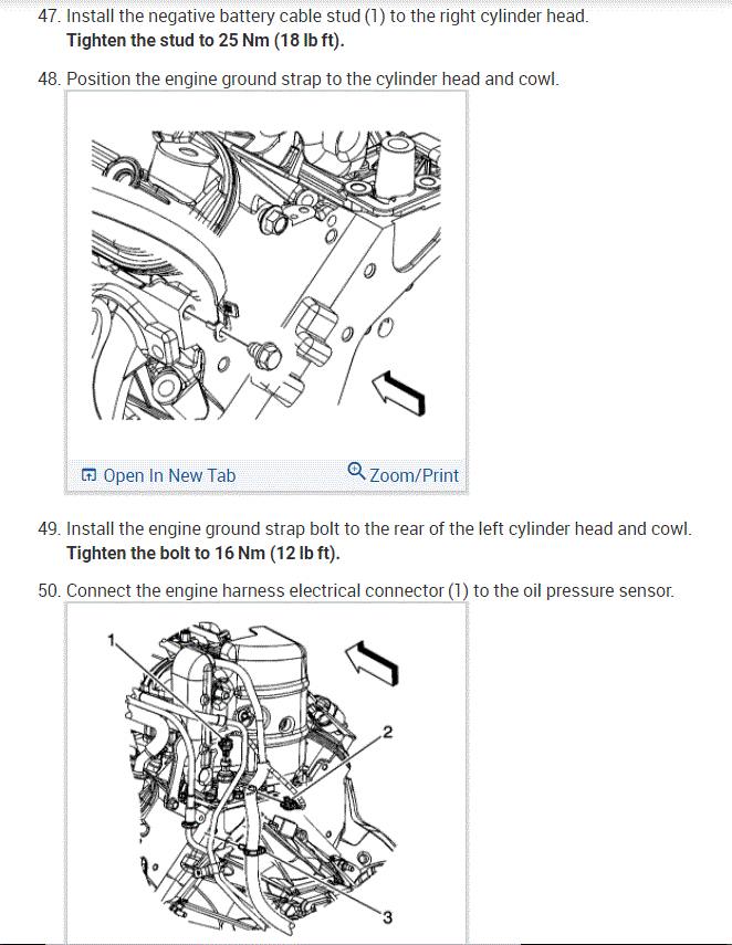
48. Connect the following electrical connectors:
- Oil pressure sensor (1)
- CMP sensor (2)
49. Position the harness ground and the engine ground strap to the block.
50. Install the harness ground bolt at the left rear of the engine block.
51. Position the harness ground, and auxiliary negative battery cable, if equipped, to the block.
52. Install the harness ground bolt at the right rear of the engine block.
Tighten the bolts to 16 Nm (12 ft. Lbs.).
53. Connect the following electrical connectors:
- ECT sensor (1)
- Electronic variable orifice switch (2)
54. Position the harness ground and negative battery cable to the block.
55. Install the harness ground bolt.
Tighten the bolt to 25 Nm (18 ft. Lbs.).
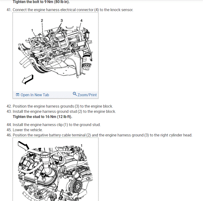
56. Connect the MAP sensor (1) and knock sensor (2) electrical connectors.
57. Connect the following electrical connectors:
- Main coil harness (1)
- Fuel injectors (2)
- ETC (3)
58. Connect the main coil harness (2) and fuel injector electrical connectors on the left side.
59. Install the generator cable to the generator; perform the following:
59.1. Install the generator cable.
59.2. Install the generator cable nut to the terminal stud.
Tighten the nut to 9 Nm (80 inch lbs.).
59.3. Slide the boot over the terminal stud.
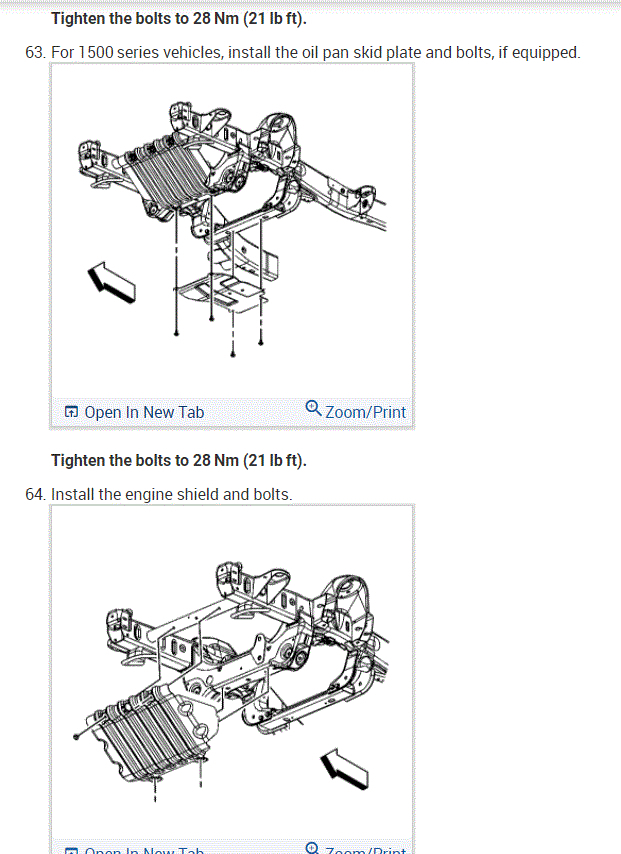
60. Install the radiator vent inlet hose to the throttle body.
61. Position the vent inlet hose clamp at the throttle body.
62. Install the engine wiring harness bracket and nut (2)
Tighten the nut to 5 Nm (44 inch lbs.).
63. Connect the following electrical connector:
- EVAP canister purge solenoid (1)
- Generator (3)
64. Install the heater hoses.
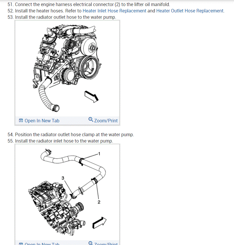
65. Open the hose clamp and install the radiator outlet hose to the water pump.
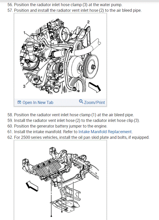
66. Open the hose clamp and install the radiator inlet hose to the water pump.
67. Install the radiator support.
68. Install the A/C compressor.
69. Remove the hood hinge bolts from the service position (2).
70. Lower the hood to the normal position.
71. Install the hood hinge bolts.
Tighten the bolts to 25 Nm (18 ft. Lbs.).
72. Remove the fender covers.
73. Fill the crankcase with the proper quantity and grade of engine oil.
74. Bleed the hydraulic clutch, if equipped.
75. Perform the CKP system variation learn procedure.
Important: After an overhaul, the engine should be tested. Use the following procedure after the engine is install in the vehicle.
76. Test the vehicle using the following procedure:
76.1. Disable the ignition system.
76.2. Crank the engine several times. Listen for any unusual noises or evidence that parts are binding.
76.3. Enable the ignition system.
76.4. Start the engine and listen for unusual noises.
76.5. Check the vehicle oil pressure gage or light and confirm that the engine has acceptable oil pressure.
76.6. Run the engine speed at about 1000 RPM until the engine has reached normal operating temperature.
76.7. Listen for sticking lifters and other unusual noises.
76.8. Inspect for fuel, oil and/or coolant leaks while the engine is running.
76.9. Perform a final inspection for the proper engine oil an coolant levels.
77. Install the engine shield.
78. Close the hood.
Check out the diagrams (Below). Please let us know if you need anything else to get the problem fixed.
Images (Click to make bigger)
Wednesday, March 31st, 2021 AT 5:06 PM
(Merged)