Hi,
As far as the replacement engine, I would only use the same year, make, and model. They are changing things so often, you may run into trouble.
As far as the cylinder head, it really needs to be removed and inspected to see what happened. Can you tell me if there is noise or another issue that leads you to believe there is a problem with the valves?
If you decide to remove the head, here are the directions. They are a bit extensive but can be done. The attached pics correlate with the directions.
_______________________________________
2007 Chevrolet Aveo L4-1.6L
Cylinder Head Replacement
Vehicle Engine, Cooling and Exhaust Engine Cylinder Head Assembly Service and Repair Removal and Replacement Cylinder Head Replacement
CYLINDER HEAD REPLACEMENT
Cylinder Head Replacement
Tools Required
* J 45059 Angle Meter
* KM-470-B Angular Torque Gage
* J 42492-A (KM-421-A) Timing Belt Adjuster
Removal Procedure
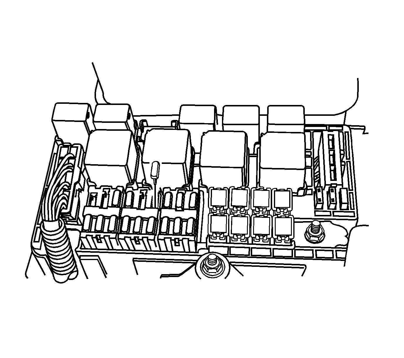
pic 1
Caution: Refer to Safety Glasses Caution.
1. Remove the fuel pump fuse.
2. Start the engine. Crank the engine after the engine stalls for 10 seconds to rid the fuel system of fuel pressure.
3. Drain the engine coolant.
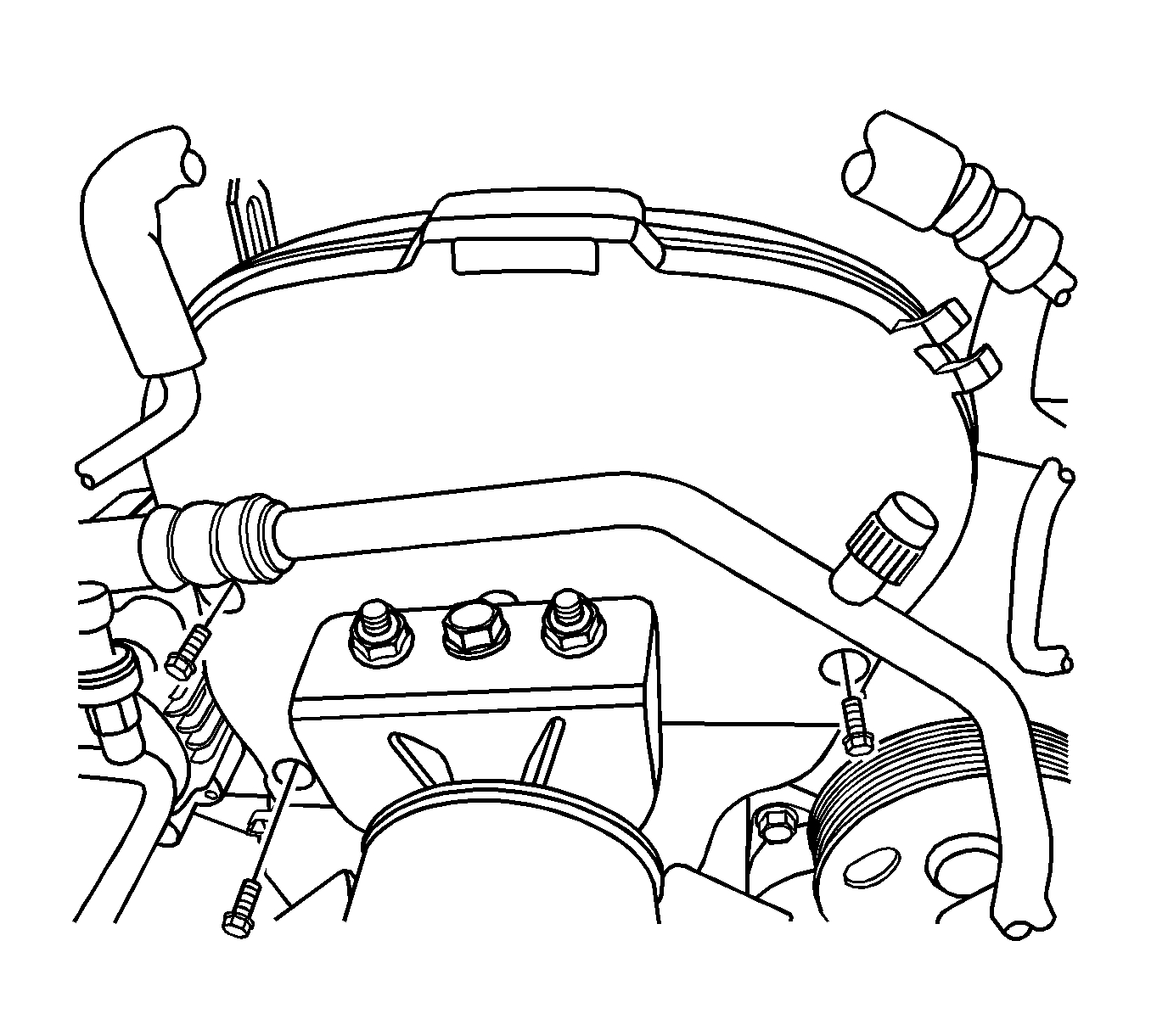
Pic 2
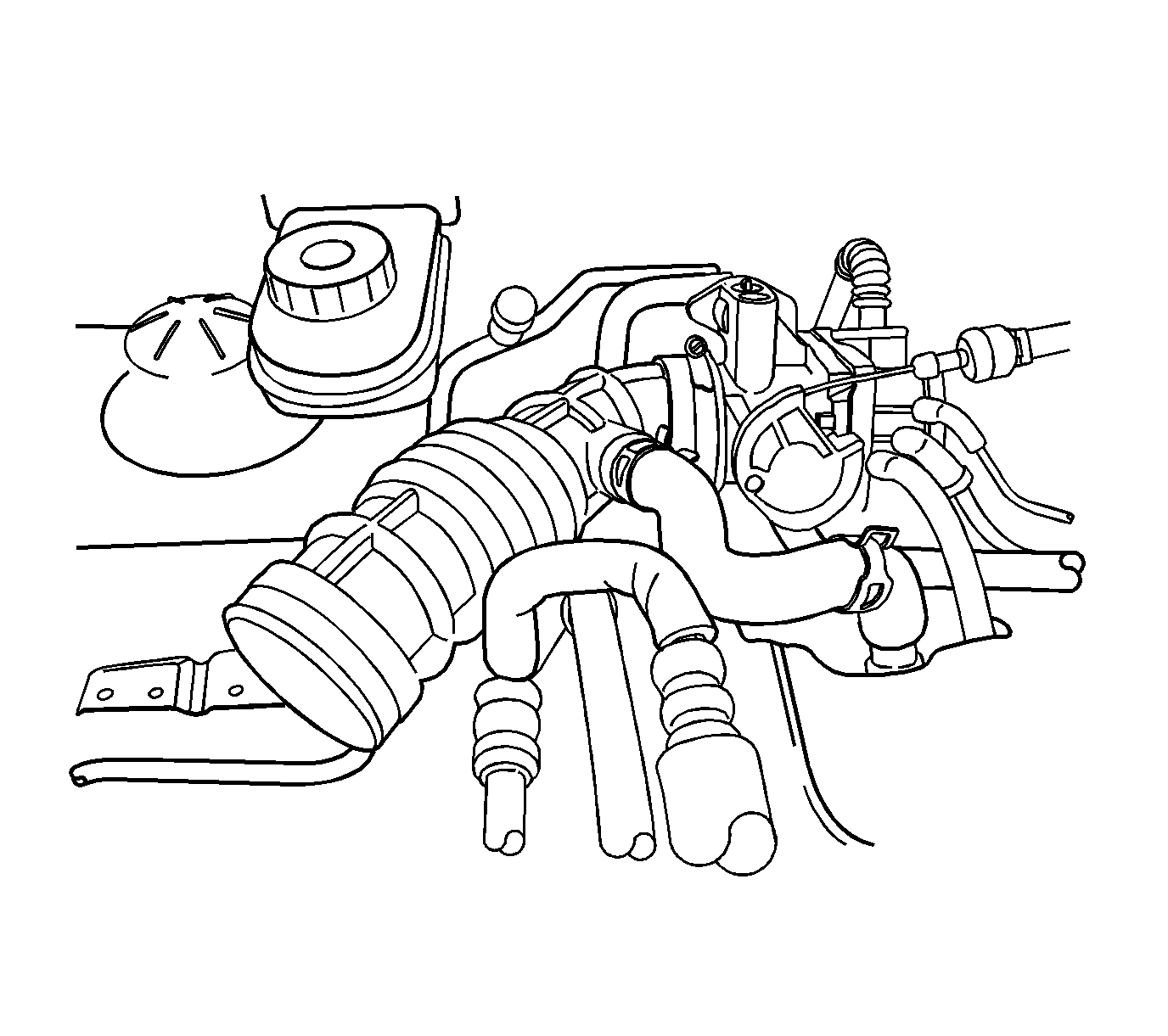
4. Disconnect the breather tube from the valve cover.
5. Disconnect the intake air temperature (IAT) sensor connector.
6. Disconnect the air intake tube from the throttle body.
Pic 3
7. Remove the air filter housing bolts.
8. Remove the air filter housing.
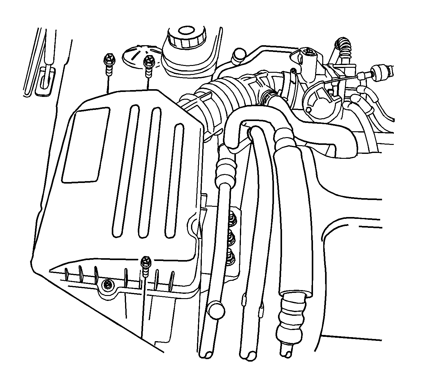
Pic 4
9. Disconnect the A/C pressure (ACP) transducer connector.
Pic 5
10. Disconnect the idle air control (IAC) valve connector.
11. Disconnect the throttle position (TP) sensor connector.
12. Disconnect the throttle cable from the throttle body and the intake manifold.
13. Disconnect the engine coolant inlet/outlet hose at the throttle body.
Pic 6
14. Disconnect the manifold absolute pressure (MAP) sensor connector.
15. Disconnect the brake booster vacuum hose.
16. Disconnect the variable geometry induction solenoid (VGIS) connector.
17. Disconnect the VGIS vacuum tank hose.
Pic 7
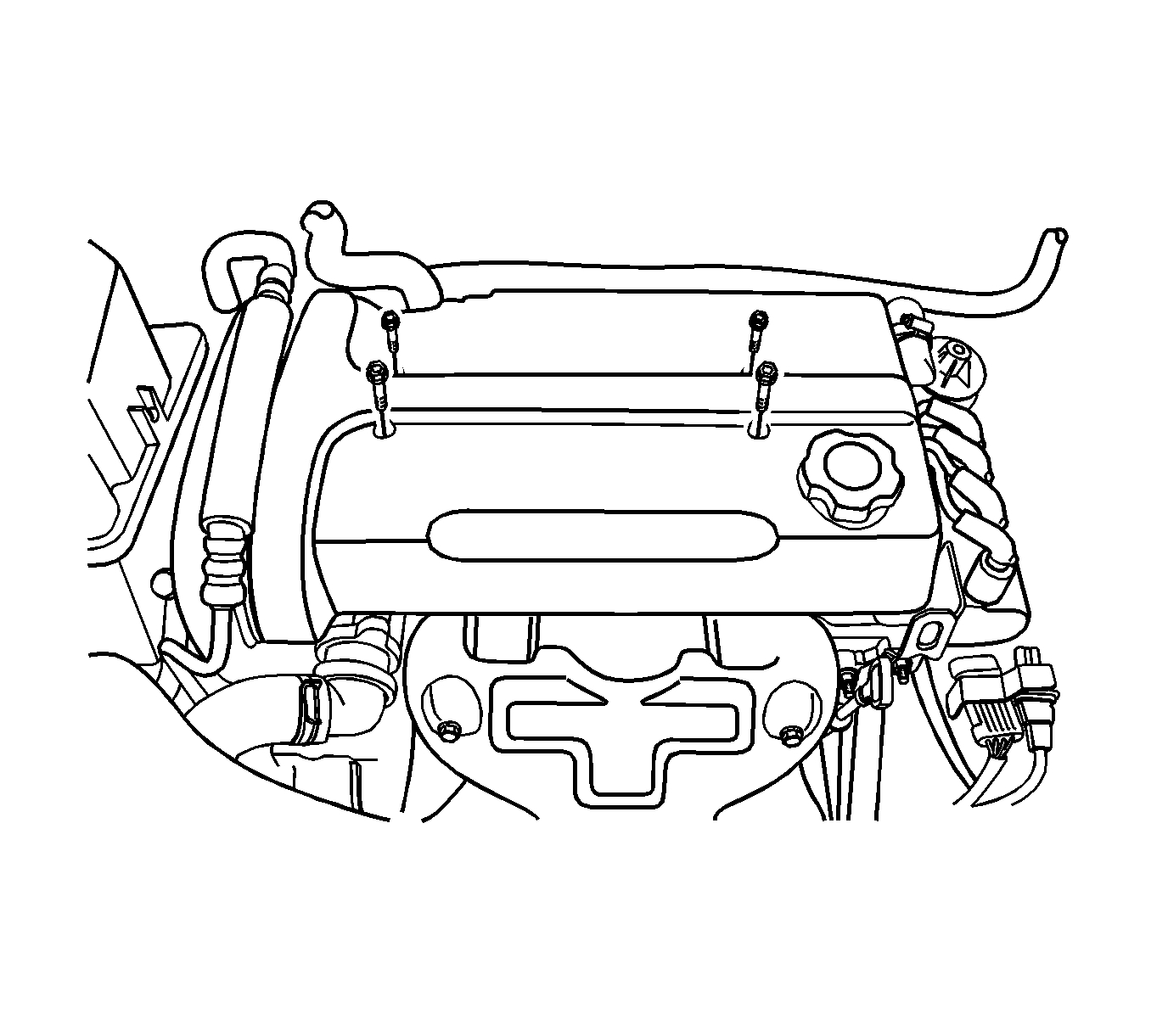
18. Remove the engine cover bolts and the cover.
19. Disconnect the breather tube from the valve cover.
20. Disconnect the crankcase ventilation tube from the valve cover.
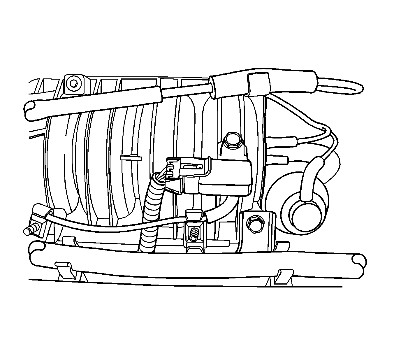
Pic 8
21. Disconnect the camshaft position (CMP) sensor connector.
22. Disconnect the ignition wires from the spark plugs.
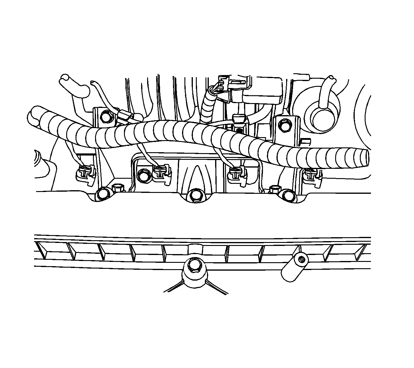
23. Disconnect the fuel injector harness connectors.
Pic 9
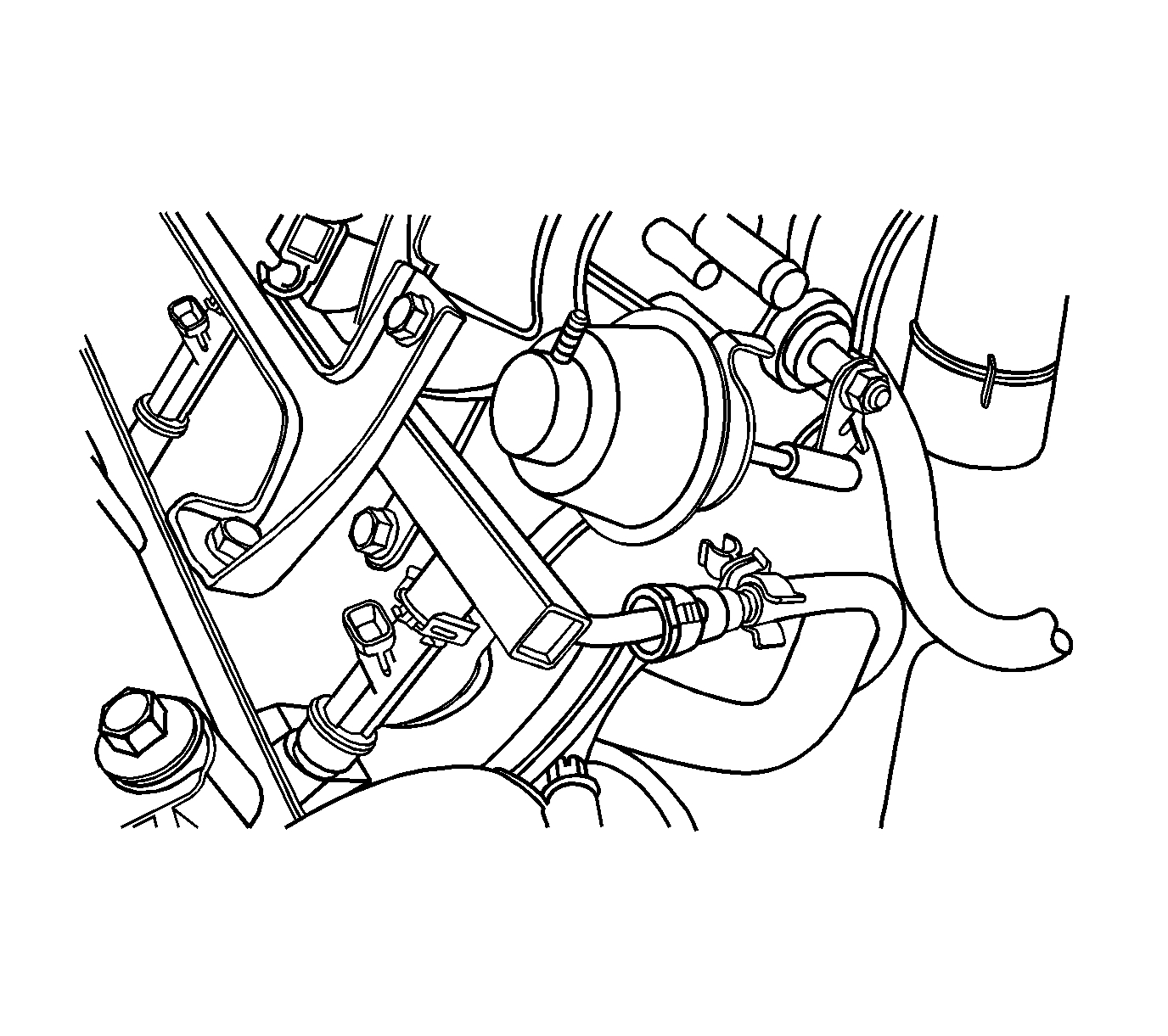
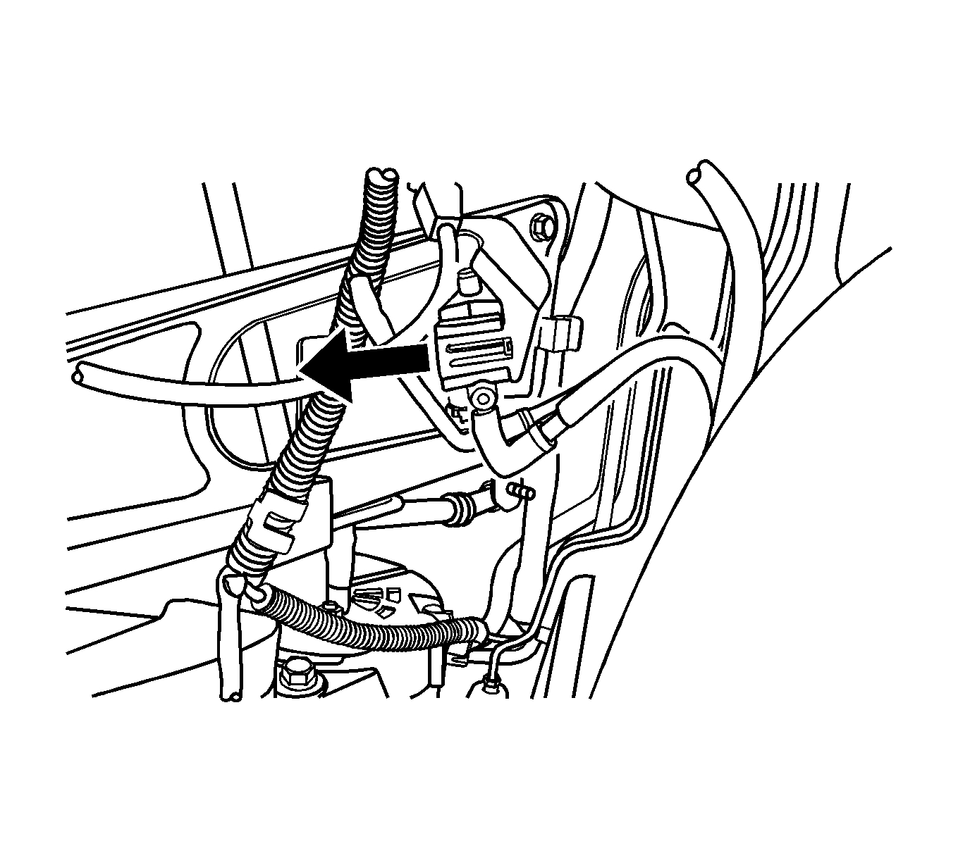
24. Disconnect the fuel line.
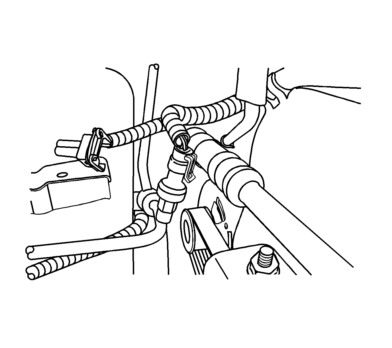
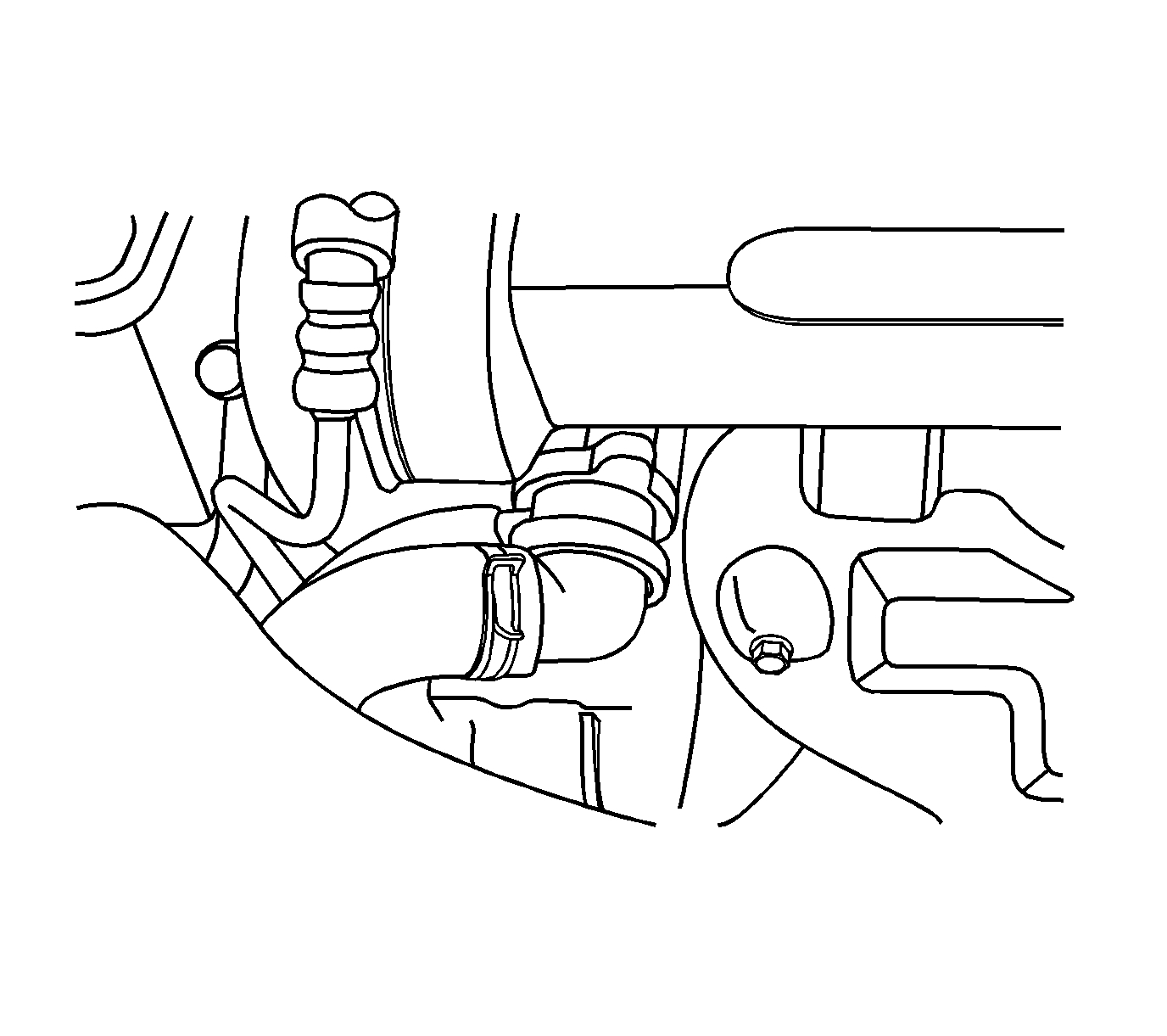
Pic 10
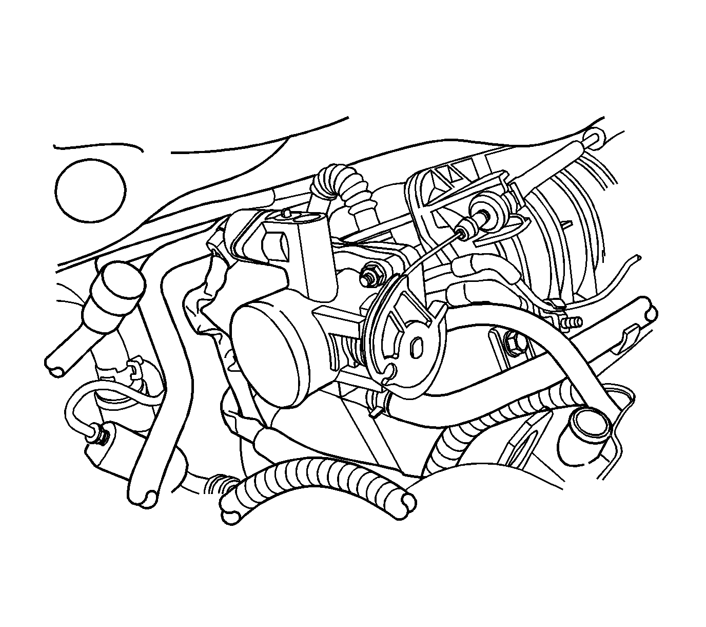
25. Remove the bracket nut from the power steering pressure pipe.
26. Remove the power steering pressure pipe.
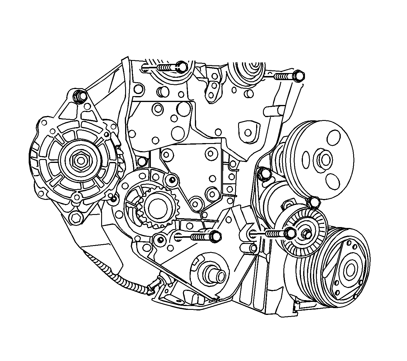
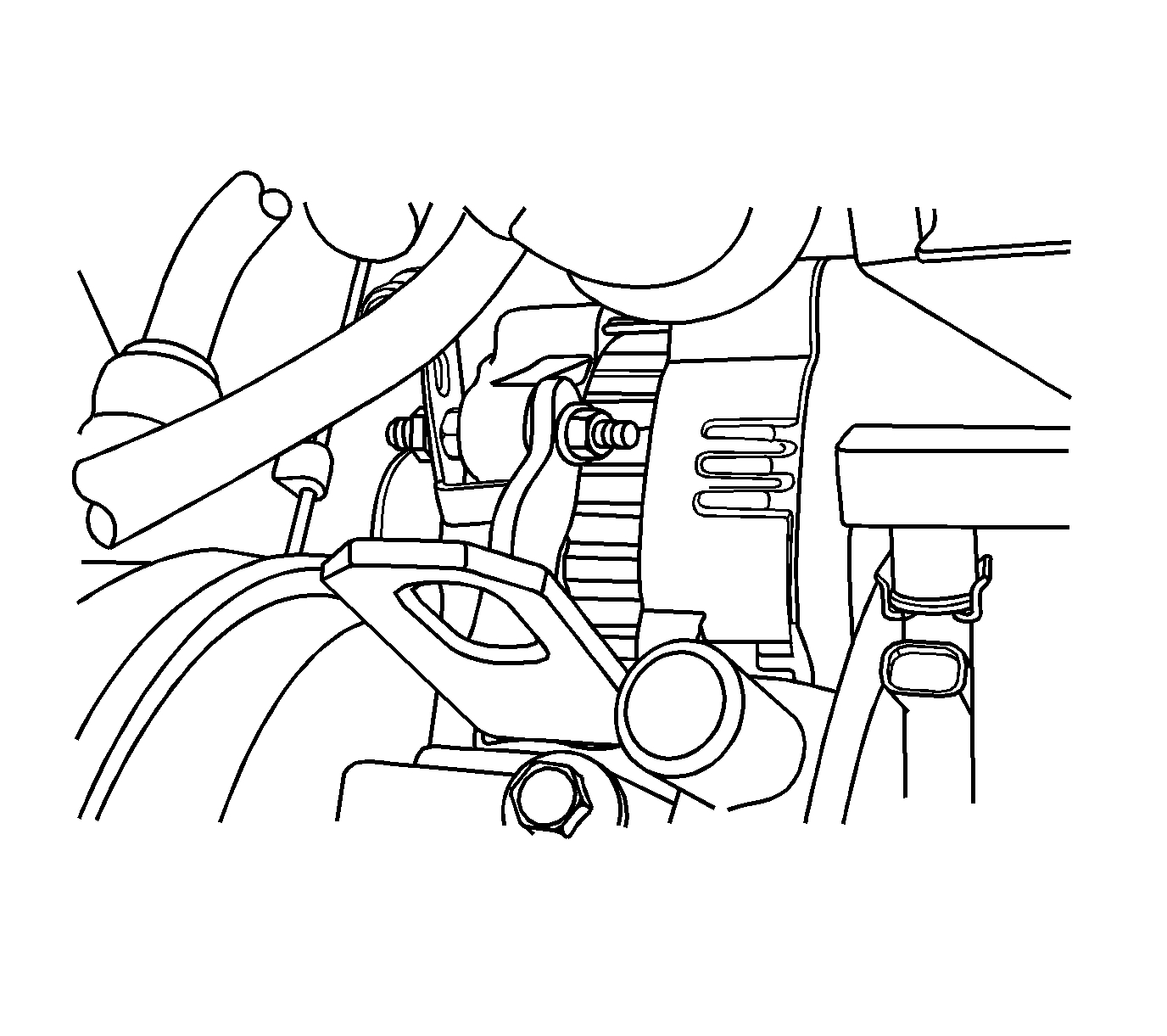
27. Remove the alternator adjusting nut.
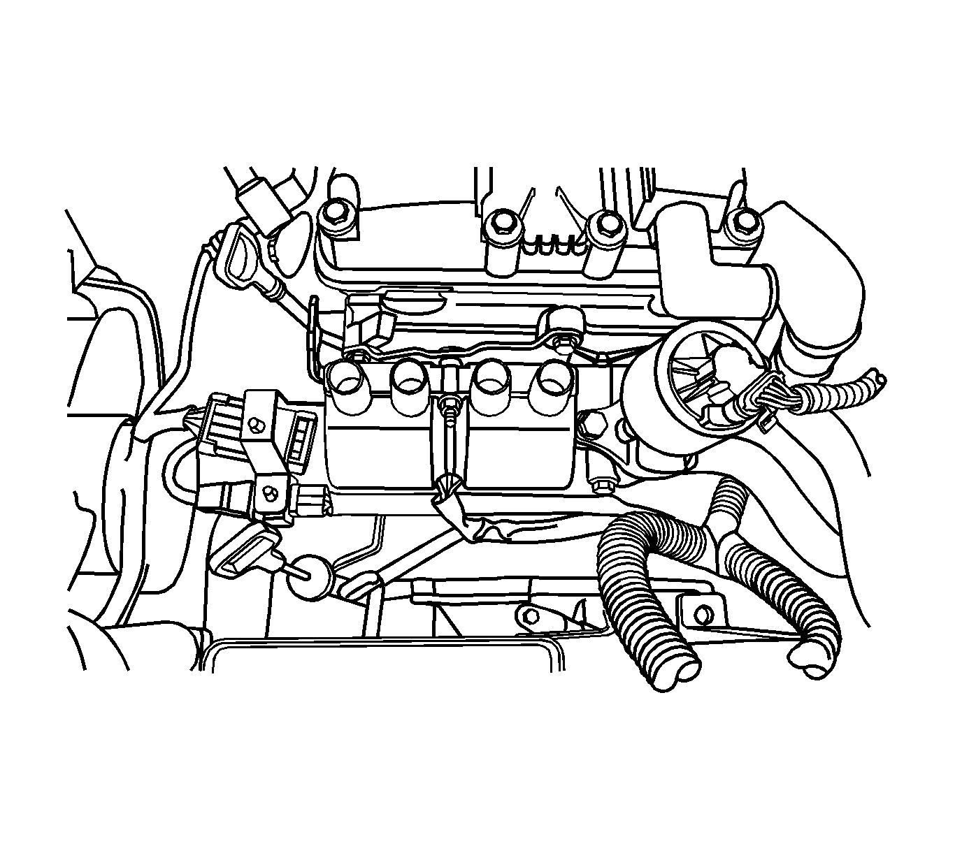
Pic 11
28. Remove the accessory drive bolt.
29. Disconnect the exhaust gas recirculation (EGR) valve connector.
30. Disconnect the ignition coil connector from the electronic ignition (EI) system.
31. Disconnect the front heated oxygen sensor (HO2S) connector.
Pic 12
32. Remove the right front wheel.
33. Remove the engine under-cover bolt and the nuts.
34. Remove the engine under-cover.
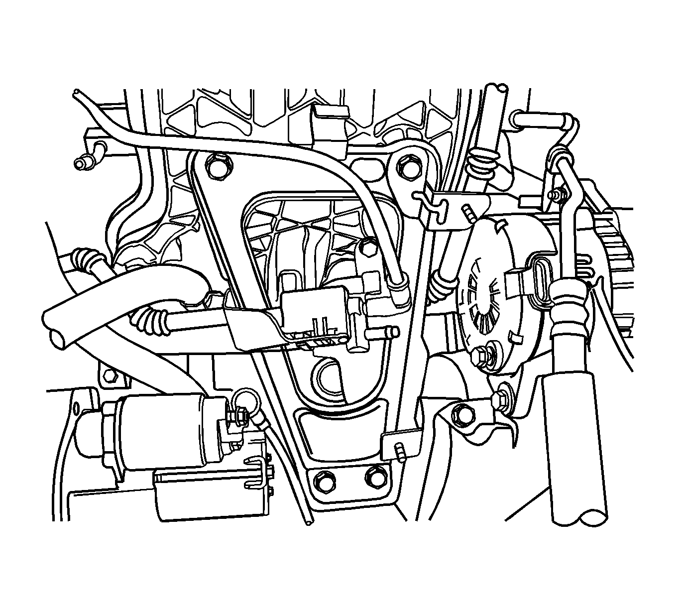
35. Remove the canister purge solenoid valve at the intake manifold support bracket.
Pic 13
36. Remove the bracket bolts from the upper intake manifold support.
37. Remove the bracket bolts from the lower intake manifold support.
38. Disconnect the connector from the engine coolant temperature (ECT) sensor.
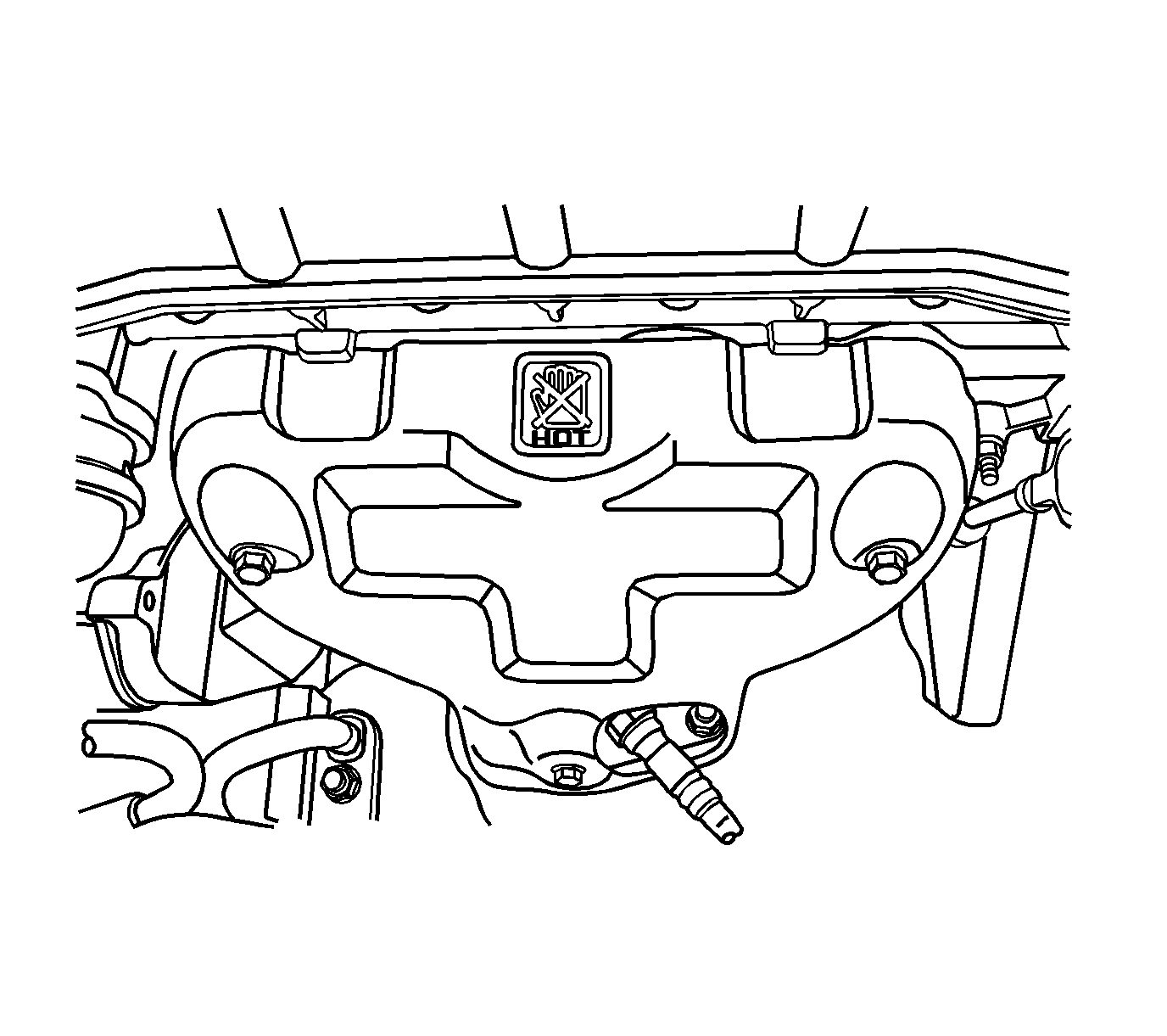
Pic 14
39. Remove the exhaust manifold heat shield bolts.
40. Remove the exhaust manifold heat shield.
41. Remove the catalytic converter.
Pic 15
42. Loosen the hose clamp on the upper radiator hose at the thermostat housing.
43. Disconnect the upper radiator hose from the thermostat housing.
Pic 16
44. Remove the cover bolts from the upper front timing belt.
45. Remove the cover from the upper front timing belt.
Pic 17
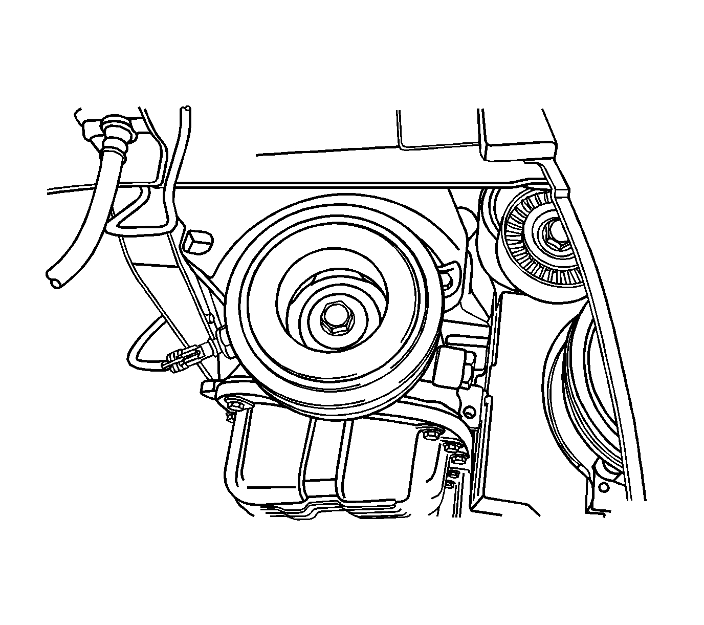
46. Remove the crankshaft pulley bolt.
47. Remove the crankshaft pulley.
Pic 18
48. Remove the cover bolts from the lower front timing belt.
49. Remove the cover from the lower front timing belt.
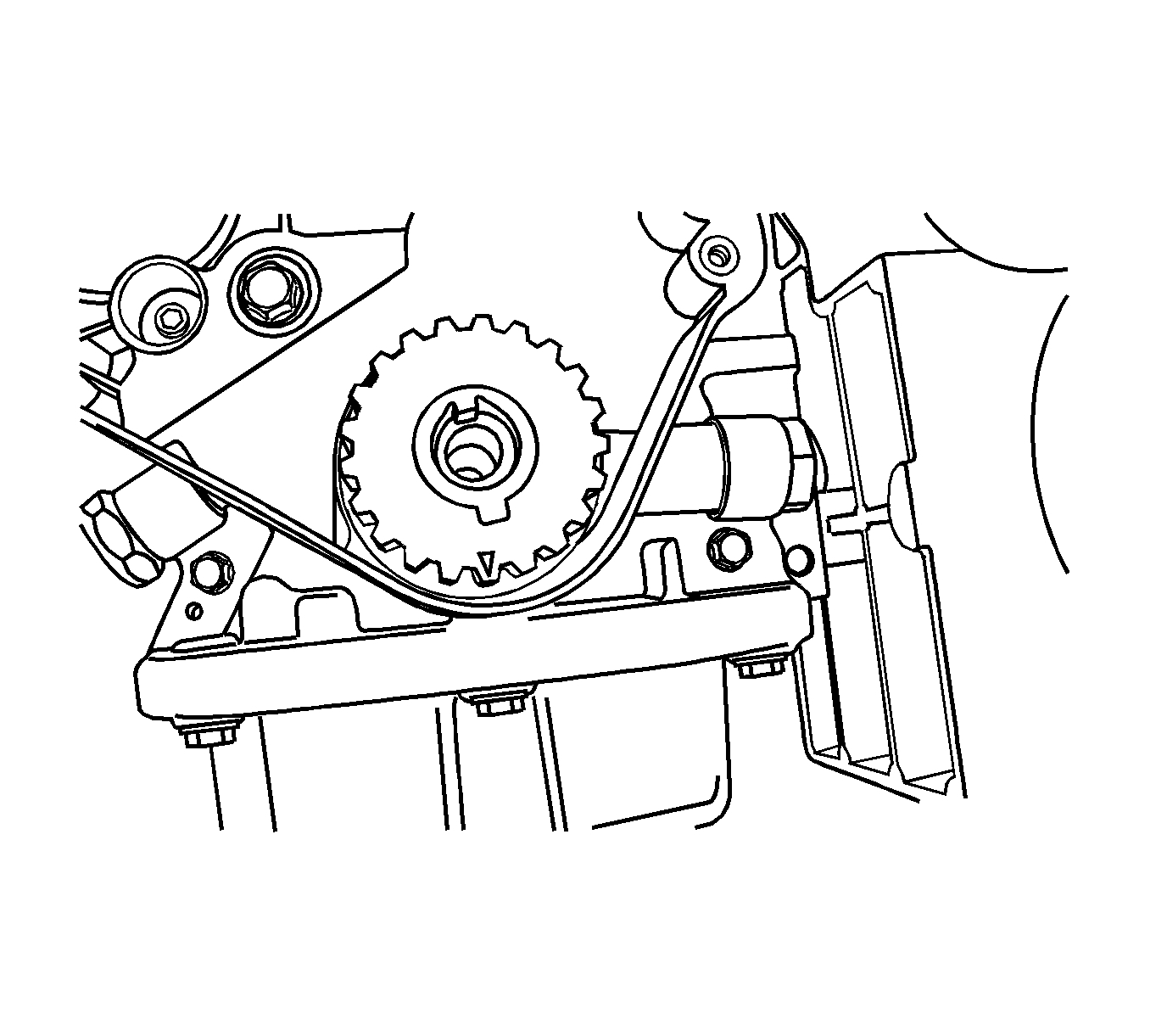
Pic 19
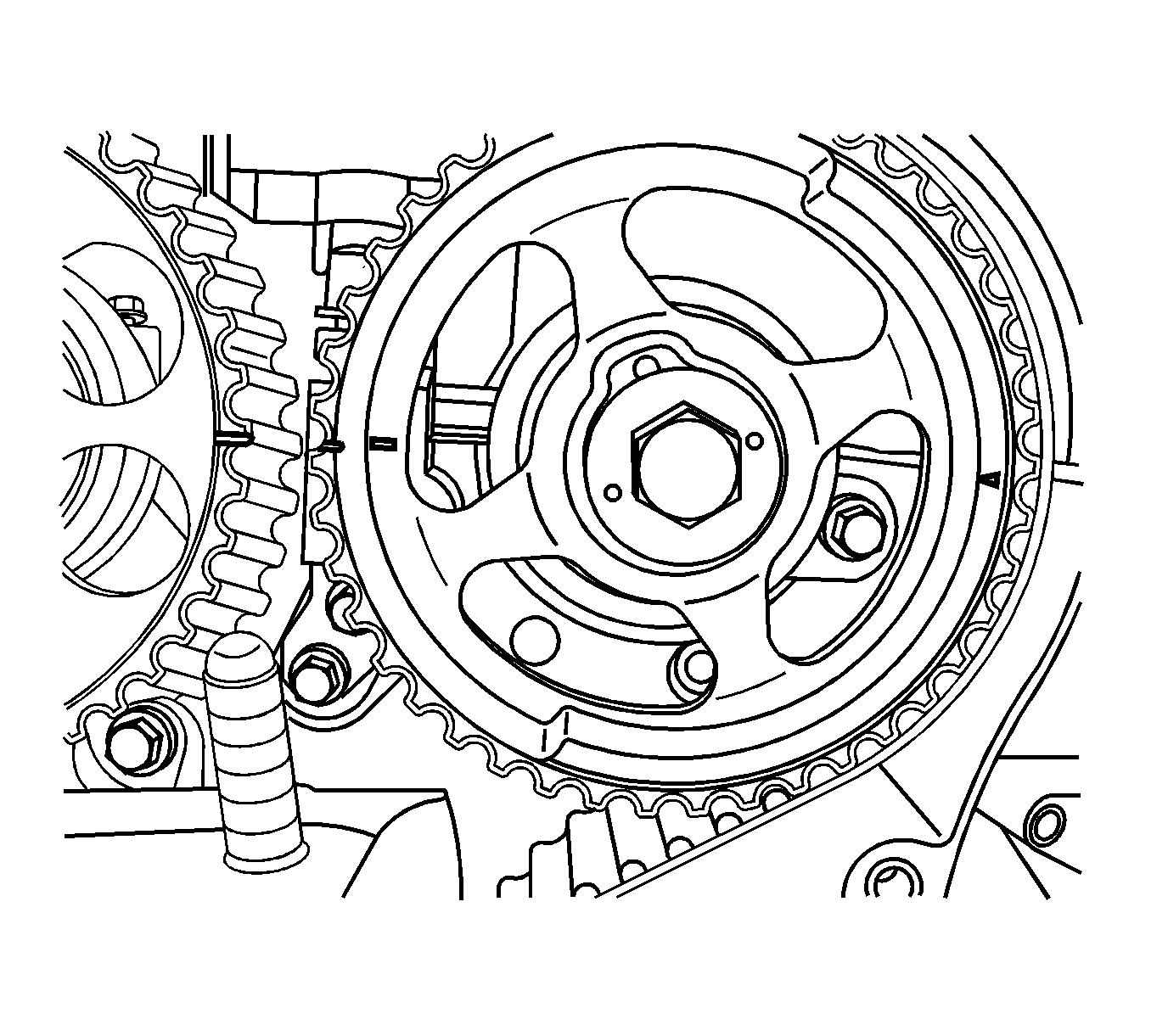
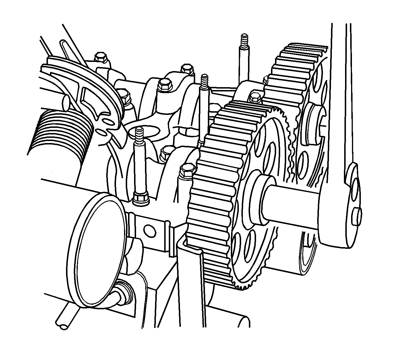
50. Align the camshaft gear timing marks.
Pic 20
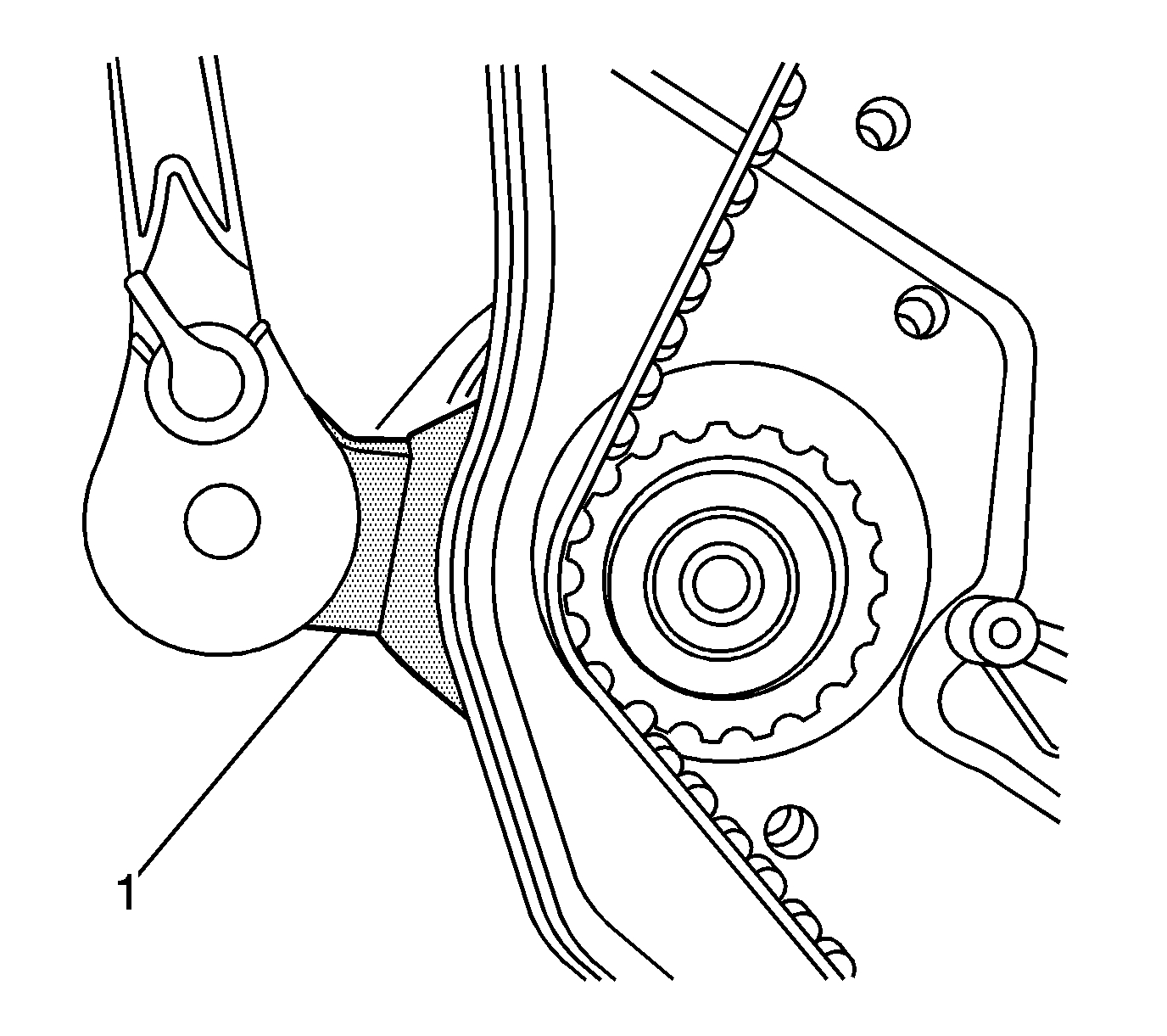
51. Slightly loosen the coolant pump retaining bolts.
52. Rotate the coolant pump counterclockwise using J 42492-A (1) to relieve the timing belt tension.
53. Remove the timing belt.
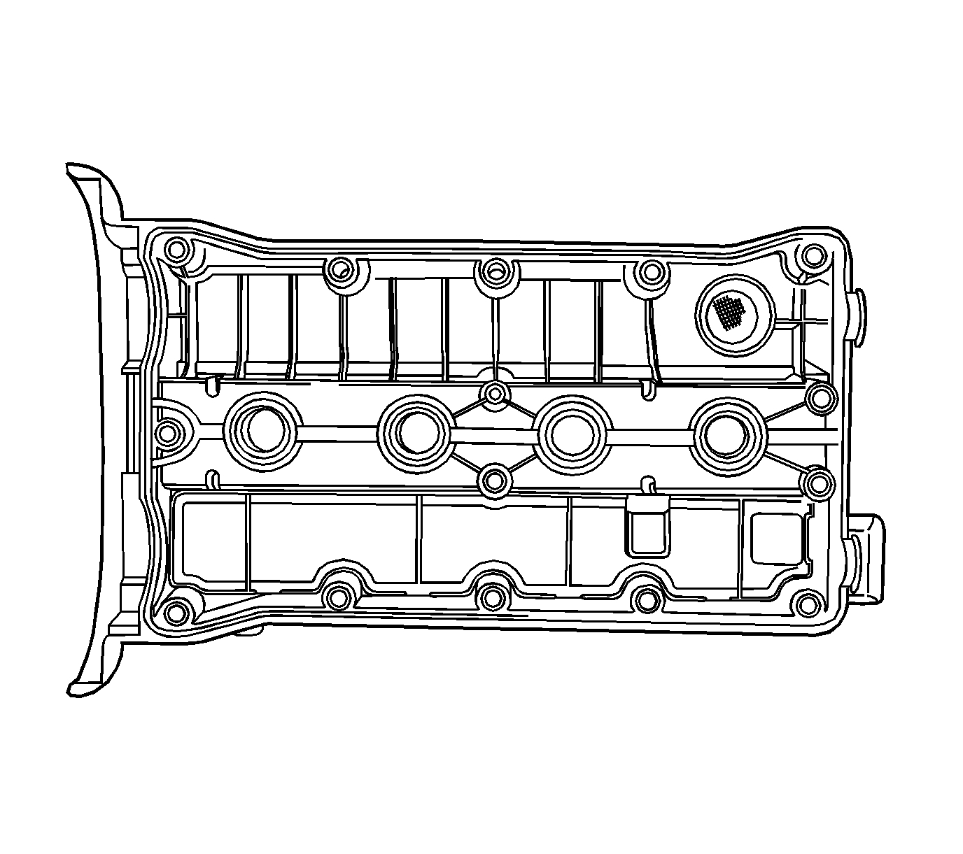
Pic 21
54. Remove the valve cover.
Notice: Use extreme care when installing the camshaft not to nick, scratch, or damage the camshaft lobes or bearing surfaces.
55. While holding the intake camshaft firmly in place, remove the intake camshaft gear bolt.
56. Remove the intake camshaft gear.
57. While holding the exhaust camshaft firmly in place, remove the exhaust camshaft gear bolt.
58. Remove the exhaust camshaft gear.
Pic 22
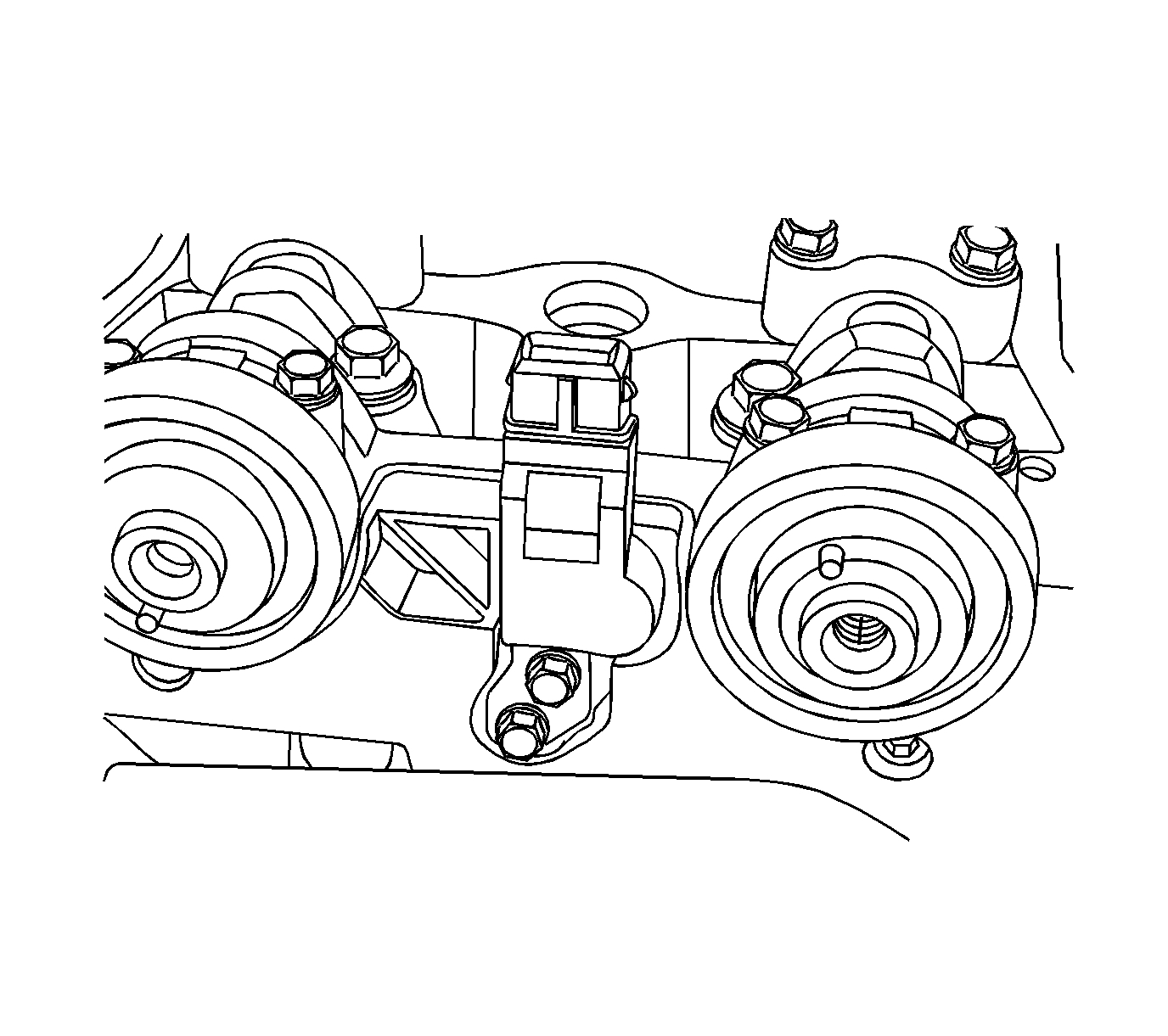
59. Remove the bolts from the timing belt automatic tensioner.
60. Remove the timing belt automatic tensioner.
Pic 23
61. Remove the camshaft position (CMP) sensor bolts.
62. Remove the CMP sensor.
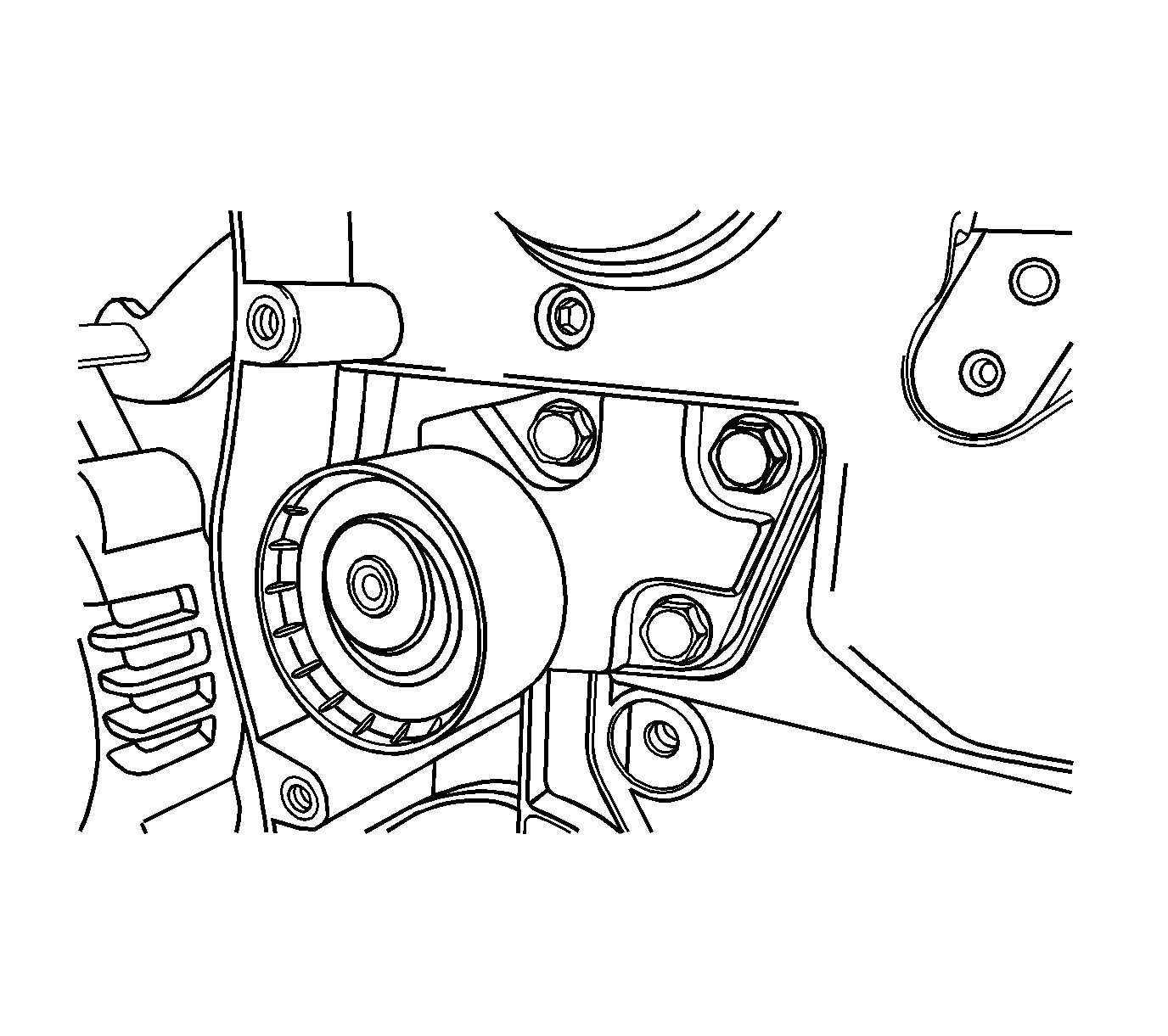
Pic 24
63. Remove the bolt from the timing belt idler pulley.
64. Remove the timing belt idler pulley.
Pic 25
65. Remove the bolts from the rear timing belt cover.
66. Remove the rear timing belt cover.
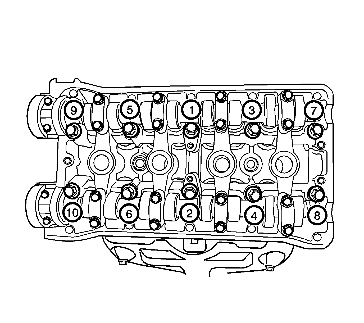
Pic 26
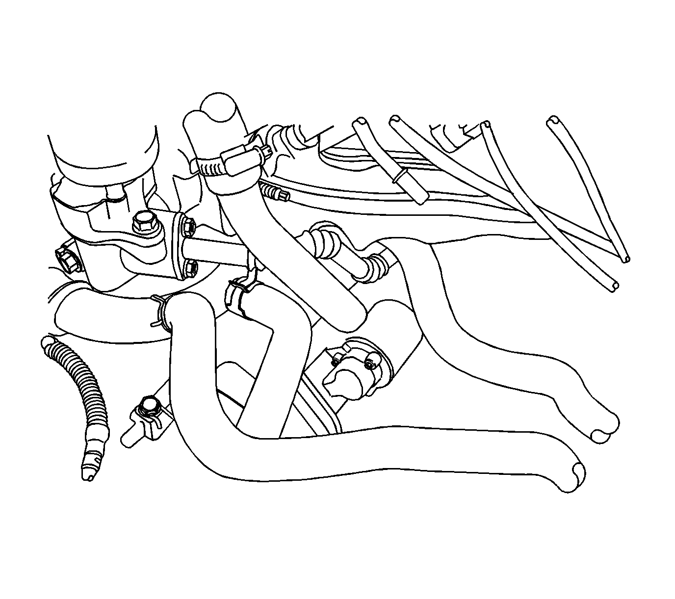
67. Disconnect the heater outlet hose from the coolant pipe.
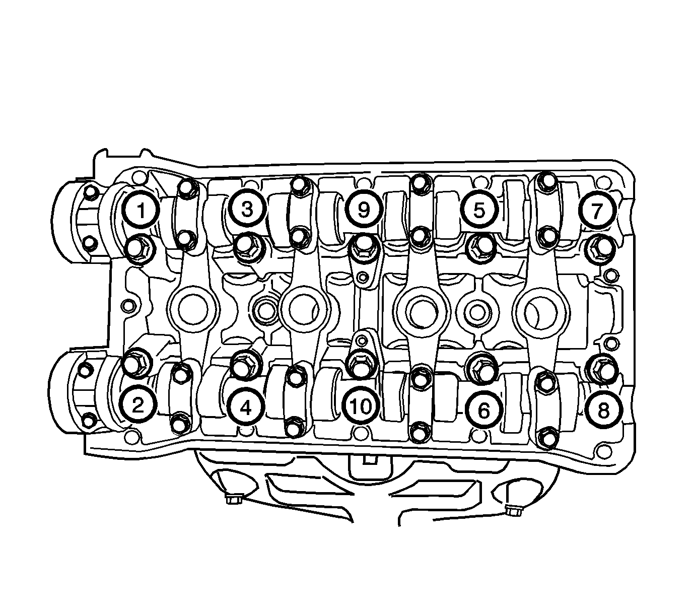
Pic 27
68. Loosen all of the cylinder head bolts gradually and in the sequence shown.
69. Remove the cylinder head bolts.
70. Remove the cylinder head with the intake manifold and the exhaust manifold attached.
Notice: Use extreme care when removing the cylinder head to prevent any engine oil, dirt, or coolant from entering the engine. Damage to the engine could result.
71. Remove the cylinder head gasket.
72. Disassembly the cylinder head, if applicable.
73. Clean and inspect the cylinder head as necessary.
Installation Procedure
1. Assemble the cylinder head, if applicable.
Pic 28
2. Install the cylinder head gasket.
3. Install the cylinder head with the intake manifold and the exhaust manifold attached.
4. Install the cylinder head bolts.
Notice: Refer to Fastener Notice.
5. Tighten the cylinder head bolts gradually and in the sequence shown.
Tighten the bolts to 25 N.M (18 lb ft). Adjust the bolts to 60 degrees plus 60 degrees plus 60 degrees plus 10 degrees using J 45059 or KM-470-B.
Pic 29
6. Connect the heater outlet hose to the coolant pipe.
Pic 30
7. Install the rear timing belt cover.
8. Install the bolts to the rear timing belt cover.
Tighten the bolts to 10 N.M (89 lb in).
Pic 31
9. Install the CMP sensor. Install the CMP sensor bolts.
Tighten the bolts to 12 N.M (106 lb in).
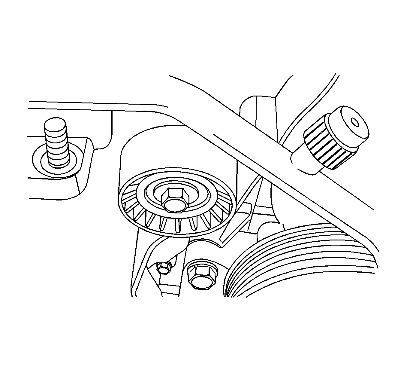
Pic 32
10. Install the timing belt idler pulley. Install the bolt. To the timing belt idler pulley
Tighten the bolt to 40 N.M (30 lb ft).
Pic 33
11. Install the timing belt automatic tensioner. Install the bolts to the timing belt automatic tensioner.
Tighten the bolts to 25 N.M (18 lb ft).
Pic 34
Notice: Use extreme care when installing the camshaft not to nick, scratch, or damage the camshaft lobes or bearing surfaces.
12. Install the intake camshaft gear.
13. While holding the intake camshaft firmly in place, install the intake camshaft gear bolt.
Tighten the bolt to 67.5 N.M (49 lb ft).
14. Install the exhaust camshaft gear.
15. While holding the exhaust camshaft firmly in place, install the exhaust camshaft gear bolt.
Tighten the bolt to 67.5 N.M (49 lb ft).
Pic 35
16. Apply a small amount of gasket sealant to the corners of the front camshaft caps and to the top of the seal between the rear valve cover and the cylinder head.
17. Install the valve cover and the valve cover gasket.
18. Install the valve cover bolts.
Tighten the bolts to 10 N.M (89 lb in).
Pic 36
Important: Ensure that the exhaust camshaft gear dowel pin is approximately in the 11 o'clock position.
19. Align the timing marks on the camshaft gear.
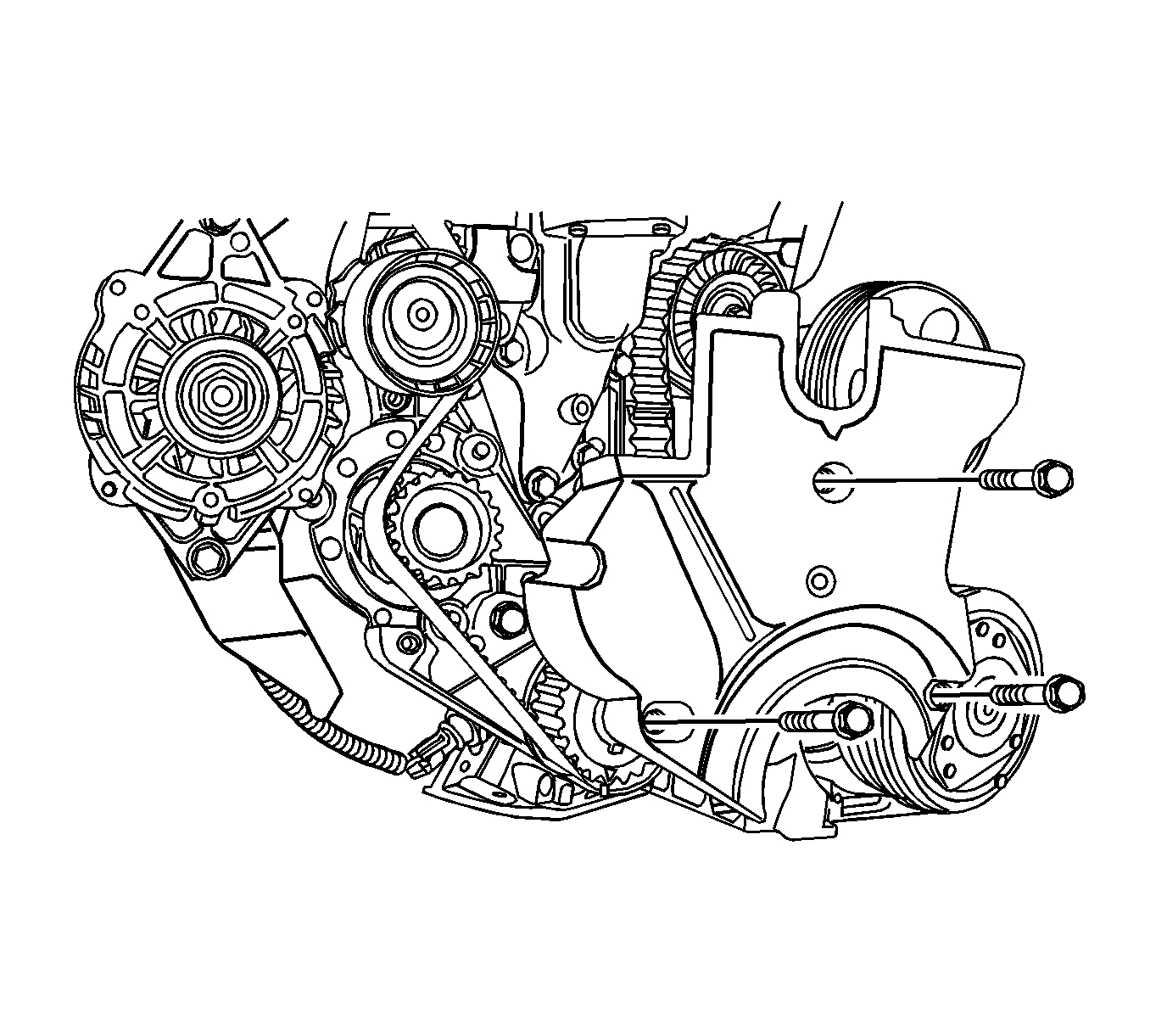
Pic 37
20. Align the mark on the crankshaft gear to the notch at the bottom of the rear timing belt cover.
Pic 38
Notice: Do not use belt dressing on the drive belt. Belt dressing causes the breakdown of the composition of the drive belt. Failure to follow this recommendation will damage the drive belt.
21. Install the timing belt.
22. Rotate the coolant pump clockwise using J 42492-A (1), to apply tension to the timing belt.
Tighten the retaining bolt to 10 N.M (89 lb in).
23. Inspect and adjust the timing belt tension.
Pic 39
24. Install the retaining bolts that secure the engine mount to the engine mount bracket.
Tighten the retaining bolts to 60 N.M (44 lb ft).
25. Install the lower front timing belt cover.
26. Install the bolts to the lower front timing belt cover.
Tighten the bolts to 10 N.M (89 lb in).
Pic 40
27. Install the crankshaft pulley.
28. Install the crankshaft pulley bolt.
Tighten the bolt to 95 N.M (70 lb ft) using a torque wrench. Using J 45059 or KM-470-B, tighten the crankshaft pulley bolt to 30 degrees plus 15 degrees.
Pic 41
29. Install the upper front timing belt cover.
30. Install the bolts to the upper front timing belt cover.
Tighten the bolts to 10 N.M (89 lb in).
Pic 42
31. Connect the upper radiator hose to the thermostat housing.
32. Connect the throttle body coolant hose to the thermostat housing.
33. Install the catalytic converter.
Pic 43
34. Install the exhaust manifold heat shield. Install the bolts to the exhaust manifold heat shield.
Tighten the bolts to 15 N.M (11 lb ft).
Pic 44
35. Connect the ECT sensor connector.
36. Install the upper bolts to the intake manifold support bracket.
Tighten the bolts to 25 N.M (18 lb ft).
Pic 45
37. Install the canister purge solenoid valve at the intake manifold support bracket.
38. Install the engine under-cover.
Pic 46
39. Connect the front HO2S connector.
40. Connect the EI system ignition coil connector.
41. Connect the EGR valve connector.
Notice: Do not use belt dressing on the drive belt. Belt dressing causes the breakdown of the composition of the drive belt. Failure to follow this recommendation will damage the drive belt.
42. Install the accessory drive belt.
Pic 47
43. Install the alternator bracket retaining nut.
Tighten the nut to 25 N.M (18 lb ft).
44. Install the alternator nut. Do NOT tighten.
Pic 48
45. Connect the fuel line at the fuel rail.
Pic 49
46. Connect the fuel injector harness connectors.
47. Connect the ignition wires from the spark plugs.
48. Connect the CMP sensor connector.
Pic 50
49. Connect the crankcase ventilation tube to the valve cover.
50. Connect the breather tube to the valve cover.
51. Install the engine cover.
52. Install the engine cover bolts.
Pic 51
53. Connect the VGIS vacuum tank hose.
54. Connect the VGIS connector.
55. Connect the brake booster vacuum hose.
56. Connect the MAP sensor connector.
Pic 52
57. Connect the engine coolant inlet/outlet hose to the throttle body.
58. Connect the throttle cable to the throttle body and the intake manifold.
59. Connect the TP sensor connector.
60. Connect the IAC valve connector.
Pic 53
61. Connect the A/C pressure transducer connector.
Pic 54
62. Install the air filter housing. Install the air filter housing bolts.
Tighten the bolts to 8 N.M (71 lb in).
Pic 55
63. Connect the air intake tube to the throttle body.
64. Connect the IAT sensor connector.
65. Connect the breather tube to the valve cover.
66. Install the fuel pump fuse.
67. Connect the negative battery cable.
68. Fill the engine cooling system.
______________________________________
Let me know if this helps or if you have other questions.
Take care,
Joe
Images (Click to make bigger)
SPONSORED LINKS
Tuesday, January 26th, 2021 AT 2:42 PM