Camshaft position sensor

Tiny
TOPSOIL
  • MEMBER
  • 2000 PONTIAC GRAND PRIX
Engine Mechanical problem 6 cyl Two Wheel Drive Automatic 100000 miles

How do I change the cam shaft position sensor. Check engine light is on and a check of computer board blames the sensor.
Wednesday, May 20th, 2009 AT 8:49 PM

13 Replies

Tiny
ZACKMAN
  • MECHANIC
  • 4,202 POSTS
Hello,

Here is a guide to help you see what you are in for when doing the job.

https://www.2carpros.com/articles/camshaft-angle-sensor-replacement

Check out the diagrams (Below) the sensor location for your car

Please let us know if you need anything else to get the problem fixed.

Cheers
Was this
answer
helpful?
Yes
No
+1
Wednesday, May 20th, 2009 AT 9:37 PM
Tiny
TOPSOIL
  • MEMBER
  • 5 POSTS
What is a MIL? Also, the engine is a 3.1L not a 3.8L, does that matter?
Was this
answer
helpful?
Yes
No
+1
Thursday, May 21st, 2009 AT 2:04 PM
Tiny
ZACKMAN
  • MECHANIC
  • 4,202 POSTS
MIL: Malfunction Indicator Light = CEL: Check Engine Light.

Difference in engine makes a big different in camshaft sensor location. In your case, the sensor is under the intake plenum.


https://www.2carpros.com/forum/automotive_pictures/55316_00grandprixcamshaft_1.jpg

Was this
answer
helpful?
Yes
No
+3
Friday, May 22nd, 2009 AT 1:22 AM
Tiny
TOPSOIL
  • MEMBER
  • 5 POSTS
MIL is P0341
Was this
answer
helpful?
Yes
No
Friday, May 22nd, 2009 AT 11:12 AM
Tiny
ZACKMAN
  • MECHANIC
  • 4,202 POSTS
This has to do with the camshaft sensor circuit, not necessarily the sensor itself. Here is the diagnostic. Unfortunately, a scan tool is necessary to properly perform the diagnostic.

Diagnostic Procedures
1. Perform On-Board Diagnostic (OBD) system check. After performing OBD system check, go to next step.
2. Operate vehicle within FAIL RECORDS data. Using scan tool, monitor SPECIFIC DTC info for this DTC until DTC test runs. If scan tool indicates that this DTC failed this ignition, go to next step. If scan tool does not indicate that this DTC failed this ignition, see DIAGNOSTIC AIDS.
3. Start engine. Using scan tool, observe CAM signal. If scan tool indicates that CAM signal is present, see DIAGNOSTIC AIDS. If scan tool does not indicate that CAM signal is present, go to next step.
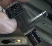
4. Turn ignition off. Disconnect CMP sensor harness connector. Turn ignition on, with engine off. Using a DVOM, check voltage between ground and CMP sensor feed circuit. If battery voltage is present, go to step 6. If battery voltage is not present, go to next step.
5. Turn ignition off. Disconnect PCM harness connector. Check CMP sensor feed circuit for short to ground or open circuit. Repair as necessary. After repairs, go to step 16. If circuit is okay, go to step 12.
6. Using a test light connected to battery voltage. Probe test light to CMP sensor ground circuit. If test light illuminates, go to step 8. If test light does not illuminate, go to next step.
7. Turn ignition off. Disconnect PCM harness connector. Check CMP sensor ground circuit for open in circuit. Repair as necessary. After repairs, go to step 16. If circuit is okay, go to step 12.
8. Start engine. Using scan tool, monitor CAM signal. Using a fused jumper wire connected to battery voltage, momentarily touch the signal circuit 5 times for about one second each time. If CAM signal changes each time the signal circuit is touched, go to step 14. If CAM signal does not change each time the signal circuit is touched, go to next step.
9. Check if fuse in jumper wire. If fuse is open, go to step 11. If fuse is okay, go to next step.
10. Check CMP sensor signal circuit for short to voltage or open circuit. Repair as necessary. After repairs, go to step 16. If circuit is okay, go to step 12.
11. Check CMP sensor signal circuit for short to ground. Repair as necessary. After repairs, go to step 16. If circuit is okay, go to next step.
12. Check for poor connections at PCM. Repair as necessary. After repairs, go to step 16. If connections are okay, go to next step.
13. Replace PCM. Program replacement PCM using required equipment. After replacing PCM, go to next step.
14. Check for poor connections at CMP sensor. Repair as necessary. After repairs, go to step 16. If connections are okay, go to next step.
15. Replace CMP sensor. After replacing sensor, go to next step.
16. Using scan tool, read and record FAILURE RECORDS data for this DTC. Operate vehicle within conditions noted in FAILURE RECORDS data. Read SPECIFIC DTC. If scan tool indicates that this DTC FAILED THIS IGN, return to step 2. If scan tool does not indicate that this DTC FAILED THIS IGN, system is okay.

Diagnostic Aid
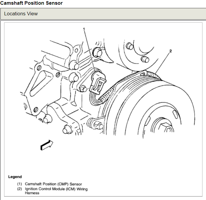
Check for incorrect harness routing near secondary ignition components, ignition coil arcing to wiring harness or ICM. Check ignition coils for cracks, carbon tracking or other signs of damage. Check for secondary ignition wire(s) arcing to wiring harness.
Check for faulty connections or damaged harness. Observe a voltmeter connected to CMP sensor signal circuit at PCM harness connector while moving all related harness and connectors. A change in voltage indicates fault location.
Was this
answer
helpful?
Yes
No
+1
Saturday, May 23rd, 2009 AT 10:24 PM
Tiny
SYLVESTER2000
  • MEMBER
  • 1 POST
2000 Grand Prix GT 3.8 non-supercharged engine was randomly stalling when at operating temperature, at any speed, at any rpm, or idling. Ran well when it ran, but RPMs would randomly drop to zero and the engine would stall. Worsening occaisional no-start condition with no spark. All power in the vehicle remained on. Sometimes would start right back up and other times would not start for 3-30 mins.
No check engine light and so no codes to pull. No traction light issues which sometimes occur when the crankshaft position sensor is failing. I didn't want to change the crankshaft position sensor because, quite frankly, it sucks. Changed the ignition control module. No change. Changed plugs and wires with no change. Finally decided to change the CPS. After much research and finding conflicting information I compiled a procedure with just the truthful parts I found and it worked beautifully and the car runs perfectly now. The CPS on these cars fail. If you have decided to change yours out it is a $35 part and is DIY with the proper information, which follows, some ingenuity, and some mechanical apptitude:
Jack and secure car. Remove passenger side tire and the plastic wheel well. The clips will probably break, so buy new ones at a hardware store later. Number and remove spark plug wires from the ignition control module so the car won't start. Remove the center bolt (15/16th inch head) from the harmonic balancer. Easiest way to do this without a doubt is to postion a flat wrench on the bolt, rest the boxed end of the wrench on the car frame in front of the harmonic balancer, and tap the starter. Remember to disable the car from starting. Bolt will break loose. To pull off the harmonic balancer use a standard harmonic balancer puller, but you will need special grade 8 bolts and washers. 1/4-28 bolts, 3" long, one inch of thread is o.K. Place a short 3/8" extension in the crank bolt hole to protect the threads. Carefully, by hand, thread the specialty bolts through the puller and into the 3 holes on the balancer that seemingly have no threads. The threads are farther in and not visible. Make sure the bolts are straight, and inserted to an even depth into the harmonic balancer. Use washers or the bolt heads will gouge and pull through the puller. I turned my specialty bolts 15 quarter turns into the harmonic balancer. Turn the puller's main bolt that it is pushing on the 3/8"extension you placed in the crank bolt's hole. Balancer came right out/off. Remove crankshaft position sensor shield. Mine was plastic. Spread the teeth that connect the shield to its bolts with a small standard screwdriver and pull/pry just a bit. No reason to remove the shield from the bolt farthest towards the rear of the car. You'll be using thread glue on the main bolt when you put in in so you can use some of that on the shield where it connects if you mess up the plastic teeth on the shield a bit. Remove the old sensor's two bolts, and save the part to torture in fire later. Bolt in new sensor, replace shield. Line up the harmonic balancer with its cotter key deal and start pulling the balancer back on with a torque wrench. To keep the engine from turning open the smalll access hole to the flywheel on the bottom of the car (two bolts). Place vicegrips on the flywheel or wedge something in the teeth. Tighten your glued main bolt to 112 lbs plus 76 degrees. You now have a car you can count on and need not worry about it dying while driving down the road. I love mine now. Just wish someone would have made these all inclusive and accurate directions for me.
Was this
answer
helpful?
Yes
No
+3
Thursday, April 12th, 2012 AT 6:40 AM
Tiny
MERLIN2021
  • MECHANIC
  • 17,250 POSTS
Any more help needed?
Was this
answer
helpful?
Yes
No
+1
Thursday, April 12th, 2012 AT 12:01 PM
Tiny
GALEN S
  • MEMBER
  • 1 POST
  • 2000 PONTIAC GRAND PRIX
  • 6 CYL
  • FWD
  • AUTOMATIC
  • 176,000 MILES
2000 grand prix gtp 3800supercharged. When im driving sometimes the car shudders and the tcs light comes on. If you shut the car off and restart it, its ok for a while. I also replaced the crankshaft sensor and camshaft sensor.
Was this
answer
helpful?
Yes
No
Monday, March 19th, 2018 AT 12:50 PM (Merged)
Tiny
DOCFIXIT
  • MECHANIC
  • 18,828 POSTS
Have you checked for codes?
Was this
answer
helpful?
Yes
No
Monday, March 19th, 2018 AT 12:50 PM (Merged)
Tiny
MIKE0615
  • MEMBER
  • 2 POSTS
  • 2001 PONTIAC GRAND PRIX
  • 6 CYL
  • 2WD
How to replace camshaft position sensor on a 2001 grand prix
Was this
answer
helpful?
Yes
No
Monday, March 19th, 2018 AT 12:50 PM (Merged)
Tiny
RASMATAZ
  • MECHANIC
  • 75,992 POSTS
CAMSHAFT POSITION (CMP) SENSOR REPLACEMENT

REMOVAL PROCEDURE

Remove the coolant recovery reservoir.
Remove the drive belt.
Disconnect the electrical connector (2) from the camshaft position sensor (1).

Remove the camshaft position sensor retaining screw.
Remove the camshaft position (CMP) sensor from the engine front cover.

INSTALLATION PROCEDURE

Install the camshaft position sensor to the engine front cover.
NOTE: Refer to Fastener Notice in Service Precautions.

Install the camshaft position sensor retaining bolt.
Tighten
Tighten the bolt to 10 N.M (89 lb in).

Connect the electrical connector (2) to the camshaft position sensor (1).
Install the drive belt.
Install the coolant recovery reservoir.
Was this
answer
helpful?
Yes
No
+1
Monday, March 19th, 2018 AT 12:50 PM (Merged)
Tiny
2CP-ARCHIVES
  • MEMBER
  • 4,542 POSTS
  • 1997 PONTIAC GRAND PRIX
  • 85,000 MILES
II have a 97 pontiac grand prix 3.8 v-6 it starts then shuts off I have fixed the mass flow censor the cam censor idiler control valve fixed a coolant leak replace the tenchner pulley its getting gas it has a spark today auto zone said that its either the mass flow a vacume leak and or has numerous misfires can you help please?
Was this
answer
helpful?
Yes
No
Monday, March 19th, 2018 AT 12:50 PM (Merged)
Tiny
ASEMASTER6371
  • MECHANIC
  • 52,797 POSTS
Autozone are parts salesman not technicians. They want to sell you parts.

What are the codes?

Check fuel pressure.

Did you try another key in case it is a security issue?

Roy
Was this
answer
helpful?
Yes
No
Monday, March 19th, 2018 AT 12:51 PM (Merged)

Please login or register to post a reply.

Sponsored links