Alternator not charging?

Tiny
TGWILSON13
  • MEMBER
  • 2009 DODGE RAM
  • 5.7L
  • V8
  • 2WD
  • AUTOMATIC
  • 2,000 MILES
I have a 2009 Dodge Ram and it will not charge I have put a brand new alternator battery and replaced the PCM and still it won't charge
Monday, November 16th, 2015 AT 1:44 PM

53 Replies

Tiny
CARADIODOC
  • MECHANIC
  • 33,727 POSTS
Measure the voltages on the three wires on the alternator. The large output wire should have battery voltage on it of 12.6 volts with the engine stopped, and it should go up to 13.75 to 14.75 with it running. The voltages on the two small terminals have to be taken with the engine running. Remember that these newer trucks see the battery is charged and allow the alternator to "let off" on the charge to save gas and not to overheat the battery. Here is the alternator wiring diagrams so you can see how the system works. Check out the diagrams (Below). Let us know what happens and please upload pictures or videos of the problem.
Was this
answer
helpful?
Yes
No
+1
Monday, November 16th, 2015 AT 2:22 PM
Tiny
TGWILSON13
  • MEMBER
  • 5 POSTS
The 2 wires on top are the voltage regulator to the PCM right
Was this
answer
helpful?
Yes
No
+3
Monday, November 16th, 2015 AT 8:31 PM
Tiny
CARADIODOC
  • MECHANIC
  • 33,727 POSTS
Nope. Building the voltage regulator into the generator, like GM and Ford do, insures you have to buy more than what must be replaced. Chrysler never did that. The voltage regulator is inside the Engine Computer where it can adjust charging voltage or turn the alternator off based on air temperature, coolant temperature, wide-open-throttle, and anything else the computer knows. This makes their alternators real simple and the circuit is easy to test.
Was this
answer
helpful?
Yes
No
+2
Tuesday, November 17th, 2015 AT 4:14 PM
Tiny
TGWILSON13
  • MEMBER
  • 5 POSTS
I checked the volts and they are ok but when I turn it on it stays at 12.1 volts and says it's not charging and I have replaced the alternator battery and PCM still they won't charge
Was this
answer
helpful?
Yes
No
Tuesday, November 17th, 2015 AT 5:36 PM
Tiny
CARADIODOC
  • MECHANIC
  • 33,727 POSTS
You gotta be more specific so I can figure out what's working and what isn't. What are you turning on and what stays at 12.1 volts? What are the three voltages on the alternator wires when the engine is running?
Was this
answer
helpful?
Yes
No
Tuesday, November 17th, 2015 AT 7:30 PM
Tiny
TGWILSON13
  • MEMBER
  • 5 POSTS
Ok I re check the connections in on top of the alternator there is a red wire in a black wire the black wire gets 12 volts but the red wire has nothing and the big wire that goes to the alternator reads 11.9 volts.
Was this
answer
helpful?
Yes
No
+1
Wednesday, November 18th, 2015 AT 12:14 PM
Tiny
CARADIODOC
  • MECHANIC
  • 33,727 POSTS
The two small wires won't have voltage until the engine is running. I need to know what you find on them when the engine is running. In particular, the brown / gray wire has to have something, but I haven't worked on this new system so I don't know if it's a voltage or a square wave pulse. If you find 0 volts with a digital voltmeter, or if the reading is bouncing around, check it with a test light. According to what I've been reading, this is the only control wire so you'll rarely find full battery voltage on it, if ever. A digital voltmeter will get confused with a pulsing square wave, but a test light will smooth it out and give you a better indication. I think the light should be dimmer than when it's connected to the battery.
Was this
answer
helpful?
Yes
No
Monday, November 23rd, 2015 AT 6:46 PM
Tiny
TGWILSON13
  • MEMBER
  • 5 POSTS
Okay I looked at the wiring diagrams and got a new TIPM that fixed it thank you so much!
Was this
answer
helpful?
Yes
No
Tuesday, November 24th, 2015 AT 8:09 PM
Tiny
DODGE2500
  • MEMBER
  • 1 POST
  • 2009 DODGE RAM
  • 5.7L
  • V8
  • 4WD
  • AUTOMATIC
  • 140,000 MILES
I bypassed the PCM with adjustable external voltage regulator. New alternator and new battery. I have 12v to the alternator but alternator still wont charge. I had a broken engine ground strap from back of cylinder heads and replaced it. Cleaned all grounds I can find.
Was this
answer
helpful?
Yes
No
Wednesday, June 23rd, 2021 AT 6:47 PM (Merged)
Tiny
SCGRANTURISMO
  • MECHANIC
  • 4,897 POSTS
Hello,

What do you mean you have 12V to alternator? The alternator is what charges the battery. In the diagrams down below I have included a wiring diagram of your vehicle's charging system for reference purposes. Here are a couple of links for you to go to:

https://www.2carpros.com/articles/how-to-check-a-car-alternator
https://www.2carpros.com/articles/car-battery-load-test

Please go through these guides and get back to us with what you are able to find out.

Thanks,
Alex
2CarPros
Was this
answer
helpful?
Yes
No
+1
Wednesday, June 23rd, 2021 AT 6:47 PM (Merged)
Tiny
UNORTHODOX91
  • MEMBER
  • 4 POSTS
  • 2009 DODGE RAM
  • 5.7L
  • V8
  • 2WD
  • AUTOMATIC
  • 137,207 MILES
No fluff.
Truck has 3rd generator on it, no charge. Battery voltage present on Gen Bat+, Bat+, and TIPM post.
Checked all wiring at PCM pins to connectors, and did voltage drop test across the power supplies.
The only discrepancies i'm seeing are:

1) Gen sense terminal on gen is showing Batt voltage, parallel to Gen Post. But when the 2-pin connector is connected and back probed, voltage is 9v. Confirmed 3v voltage drop across Batt+ and pin-2 (red/grey).
I suspected resistance in wire but continuity checked out. I pull off PCM connector and turned key on and observed the same 9v coming from the PCM male pin corresponding to pin-2. I checked pin-10 and pin-29 as they’re fused bat+ feeds and I’m getting Bat+ voltage at the connector. Are my suspicions of resistance in the PCM causing the 3v drop? Or is it getting 9v from somewhere and spitting it back out? No info online on PCM voltage specs.

2) Pin-1 is the Gen field control. The PCM uses pwm/square waves to activate field. When I tried to measure duty cycle with my dmm, I would get sporadic duty readings, never holding for more than 2 seconds. When I tried to live test the Gen duty cycle via scan tool(key on engine off) I would set duty cycle to 50% and would read sporadic readings across the range. Unsuccessful bypass with pin-1 (br/gy) to bat negative.

Scan tool states duty cycle @ 100% while running, but Gen Post pushing batt+ voltage. Target voltage is at 14.3v.
Was this
answer
helpful?
Yes
No
Wednesday, June 23rd, 2021 AT 6:48 PM (Merged)
Tiny
KASEKENNY
  • MECHANIC
  • 18,907 POSTS
I am not sure I understand where you are finding the 3 volt drop. Is this on the wiring or are you saying you are finding this internal to the PCM?

The reason is, this generator sense circuit is what the generator sends back to the PCM so the PCM can compare that to the B+ it is getting from the TIPM. When they are not the same it commands the regulator to increase the voltage.

Sounds like the PCM (regulator which is internal to the PCM) is not able to command the voltage to increase.

Let me know if I am not understanding where you are checking this voltage. However, the fact that you have 9 volts on the sense circuit is where your issue is.
Was this
answer
helpful?
Yes
No
+1
Wednesday, June 23rd, 2021 AT 6:48 PM (Merged)
Tiny
UNORTHODOX91
  • MEMBER
  • 4 POSTS
Hello and thank you for your response.

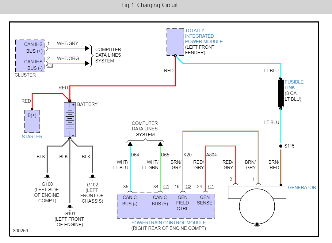
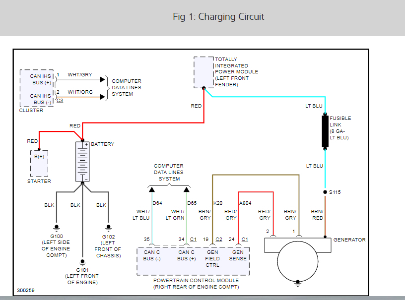
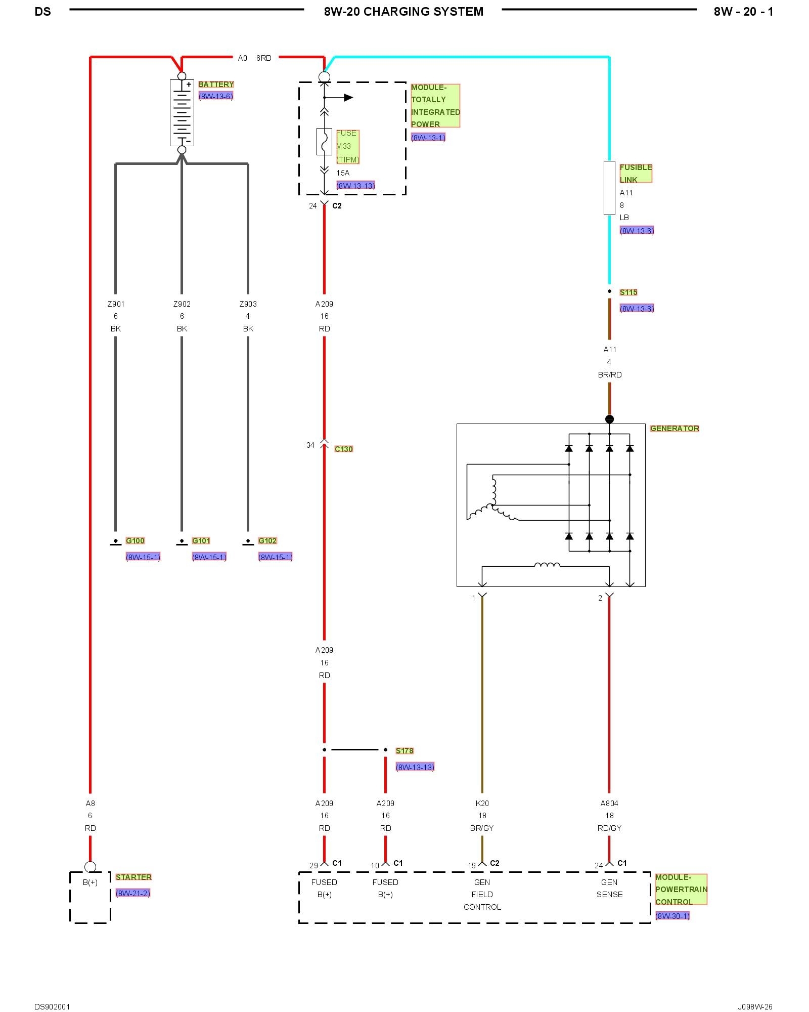
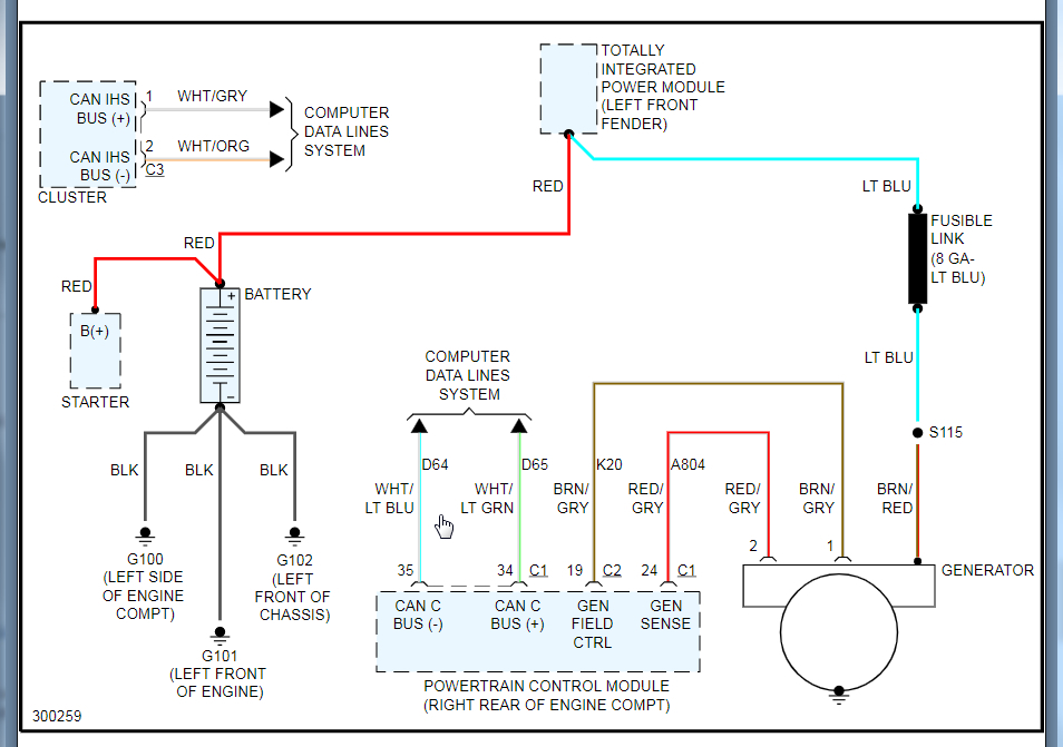
To clarify, I am picking up the 9v in the wiring, but if I recall correctly, I also disconnected connector-1 of the PCM, turned the key to the "on" position, and measured 9v from pin-24, which corresponds to the Gen sense. Which is kind of odd since the B+ connections go thru connector-1.

Anyhow, today I searched for a 5v reference off the throttle body and only picked up mV's. I then proceeded to back probe the connectors and performed a voltage drop test on all B+ and grounds going to the PCM. Nothing but that 9v discrepancy showed.

It's an odd situation since it seems as though the computer is detecting the low voltage and is trying to push 100% duty on the field, but cant signal to the gen put out the target 14.3v.
I'm banging my head trying to avoid making an assumption on the PCM, but it keeps looking like the culprit.

Testing performed:
-Continuity
-Voltage Drop
-Tracer (power probe etc)
-Gen by-passing (ineffective)
-5v reference
-Scan tool (live data & live test)
-Duty cycle measurements on Gen connector
-visually inspected and wiggled Batt cables, grounds, and wiring (accessible ones).
-Powertrain verification test
-Transmission verification test
-Changed pigtail since the prior would lock the red tab.
Had to keep charging battery since it would run down to 7v @ 100% duty cycle. It makes no sense!

I haven't opened the wiring harness to investigate if the suspected wire is causing the issue since I performed a continuity test and power probe etc tracer through it. But I feel like that's the only stone left unturned.
Was this
answer
helpful?
Yes
No
Wednesday, June 23rd, 2021 AT 6:48 PM (Merged)
Tiny
KASEKENNY
  • MECHANIC
  • 18,907 POSTS
If all your B+ are 9 volts it sounds like you may have a ground issue. You can check and clean the grounds but to confirm this, you can just back probe the grounds with a safety pin and run them to the closest stud on the engine block just to test this. It will take the easiest path to ground so if there is a ground issue, this will clear it up and then you will be able to track down the issue.
Was this
answer
helpful?
Yes
No
+1
Wednesday, June 23rd, 2021 AT 6:48 PM (Merged)
Tiny
UNORTHODOX91
  • MEMBER
  • 4 POSTS
I went through all 4 connectors and voltage drop tested all the B+ and grounds. All grounds were good and the B+ wires showed battery voltage as intended, but the only 9v is coming from the gen sense. No other circuit is showing 9v. I’m also not showing a 5v reference on the throttle body connector. I already ordered the PCM # RL150390AE.
Was this
answer
helpful?
Yes
No
Wednesday, June 23rd, 2021 AT 6:48 PM (Merged)
Tiny
KASEKENNY
  • MECHANIC
  • 18,907 POSTS
I think you nailed it. Let us know what happens after you get the PCM in there. Thanks for the update.
Was this
answer
helpful?
Yes
No
+1
Wednesday, June 23rd, 2021 AT 6:48 PM (Merged)
Tiny
KURTIS WEST
  • MEMBER
  • 2 POSTS
  • 2007 DODGE RAM
  • 5.7L
  • V8
  • 4WD
  • AUTOMATIC
  • 175,480 MILES
Truck listed above is the 1500.

Started off with a intermittent blower motor. Figured it was the resistor so I replaced that. However, today intermittent issue happened again. Smacked blower and it kicked on.

This is the issue though, when the blower is set to max the voltage gauge goes from a click above half which I believe is 13 or 14v to just below half. When it does this my lights dim, motor slows down and rpm's drop.

I'm believing that the blower motor is bad and needs to be replaced. BUT starting today the voltage is staying just barely above half and at a stop it will try to dip to half or below even with blower off.

Had O'reillys, AutoZone and Advanced Auto all test my battery, alternator and starter.

Battery came back at 12.3.
Alternator came back at 14.5 and apparently diodes and regulator got a green light.
Starter is good as its brand new.

Could the blower even while off be causing a parasitic draw on the battery?
Can the alternator state it's good but is actually going out while driving?

About a week ago I had a dtc that read voltage below 13 while above 2,000 rpm's.
Which I would assume it means while under load and driving the running volts dipped below 13.

Any help would be appreciated. I know I stated a lot but I wanted to help describe the situation as in depth as possible as it's hard to diagnose via online.
Was this
answer
helpful?
Yes
No
Wednesday, June 23rd, 2021 AT 6:48 PM (Merged)
Tiny
CARADIODOC
  • MECHANIC
  • 33,727 POSTS
The most common alternator failure is worn internal brushes, and those always start out as an intermittent no-charge problem that gets progressively worse over weeks and months. The brush assembly can be replaced for around $12.00. The next most likely suspect is a break in the field wire between the Engine Computer and the alternator. These can be found with voltage tests, but to be valid for diagnosing this, those readings have to be taken while the problem is occurring.

The heater fan motor won't have any effect on this when it's turned off, and from what you described, the best suspect is worn brushes in that motor. Hitting it and it starts running is the big clue there. I'm working with another fellow for the same problem right now. His looks like it's going to be related to overheated connector terminals on the back of the HVAC controller, but his symptoms are a little different too.

Engine idle speed can be affected by an intermittent charging system. When it cuts out, system voltage drops, and that is the voltage applied to the injectors. With less voltage across them when the computer pulses them open, it will take a little longer for their valves to be pulled open, so you'll get less gas. If this condition lasts long enough, the computer will pulse the automatic idle speed motor to get idle speed back up, and you'll see short-term fuel trim numbers increase to get the volume of fuel back up to where it should be.

If you can catch the charging problem acting up, measure the voltages on the two smaller terminals on the back of the alternator and tell me what you find. These must be taken with the engine running. It would also be helpful if you can see what those voltages are when the system is charging normally.
Was this
answer
helpful?
Yes
No
+1
Wednesday, June 23rd, 2021 AT 6:48 PM (Merged)
Tiny
UNORTHODOX91
  • MEMBER
  • 4 POSTS
Update:

So after running the aforementioned tests, I concluded that the PCM’s voltage regulator had failed, and required replacement.
I ordered a new PCM from mopar (part # RL150390AE). I soon learned that trying to “program” a pcm via scan tool was a futile venture. Being my first new PCM, it took me a while to determine that it required a flash of the corresponding vehicle file from TechAuthority via WiTech 2.0 (j2534).
After flashing the PCM and performing relearns, the truck started right up and the generator was pushing 14.3v! Success!

Hope this provides insight for anyone else dealing with the same issue.
Thanks for the input and boost in confidence venturing in unknown territory.
Was this
answer
helpful?
Yes
No
+2
Wednesday, June 23rd, 2021 AT 6:48 PM (Merged)
Tiny
KURTIS WEST
  • MEMBER
  • 2 POSTS
So I noticed some minor burns on the fusible link so I replaced it now it charges thanks
Was this
answer
helpful?
Yes
No
Wednesday, June 23rd, 2021 AT 6:48 PM (Merged)

Please login or register to post a reply.

Sponsored links