Camshaft timing?

Tiny
SHIMMAN35
  • MEMBER
  • 1989 NISSAN TRUCK
  • 6 CYL
  • 2WD
  • AUTOMATIC
  • 122,081 MILES
I have a 1989 nissan pickup with timing issues. I had to replace the water pump and upon doing so, my dad attempted to remove the crankshaft pulley becuase the haynes manual said to. I think he messed the timing up. He couldnt get it off so now he cut the bottom timing belt cover off completely, yeah cut it off, it will not be going back on and this had the timing mark on it. I still do not know how it got out of time, the only thing messed with the crankshaft pulley. My? Is since there is no mark (on the bottom timing belt cover which is no more) but there are the marks on the crankshaft pulley itself. If all the marks were in tact and corrcet and I shot a light on it, how does one adjust the timing to get it back on the TDC/marks. There is a square looking, I guess distributor but its not the round style. Its a VG301 engine V6. What do I do and mainly what Do I turn to advance or retard the timing?
Do you
have the same problem?
Yes
No
Thursday, November 18th, 2010 AT 6:58 PM

18 Replies

Tiny
SHIMMAN35
  • MEMBER
  • 4 POSTS
Also my transimission is shifting correctly and the enigne when I try to climb a hill is pinging like a bad gas ping does but its supper loud. I assume this is all tied to the timing issue?
Was this
answer
helpful?
Yes
No
Wednesday, November 29th, 2017 AT 5:38 PM
Tiny
KHLOW2008
  • MECHANIC
  • 41,815 POSTS
To adjust the timing, loosen the distributor holding bolts and rotate clockwise or anticlockwise it to get the desired ignition timing.

This will help

https://www.2carpros.com/diagrams/nissan/pickup/1989

You need the marker on the timing belt cover to get the correct timing. Without the marks, you would have to remove the pulley to check the crank pulley timing mark for TDC and then make your mark on the cover.

On the pulley, the first mark on the left of pulley is 0 with increment of 5 degrees.

Ignition timing should be 10-14 degrees at 650-800 rpm.

The pinging indicates the ignition timing is most likely too advanced.
Was this
answer
helpful?
Yes
No
Wednesday, November 29th, 2017 AT 5:38 PM
Tiny
RASMATAZ
  • MECHANIC
  • 75,992 POSTS
The Knock sensor might not be retarding the timing when it senses detonation/spark knock
Was this
answer
helpful?
Yes
No
Wednesday, November 29th, 2017 AT 5:38 PM
Tiny
SHIMMAN35
  • MEMBER
  • 4 POSTS
So I guess the square looking thing that all the plug wires are going to is the distributor and can also turn like the round style ones can?
Was this
answer
helpful?
Yes
No
Wednesday, November 29th, 2017 AT 5:38 PM
Tiny
SHIMMAN35
  • MEMBER
  • 4 POSTS
Thanks for all your input!
Was this
answer
helpful?
Yes
No
-1
Wednesday, November 29th, 2017 AT 5:38 PM
Tiny
QUICKLY
  • MEMBER
  • 1 POST
  • 1988 NISSAN TRUCK
  • 4 CYL
  • 4WD
  • MANUAL
  • 130,000 MILES
I am replacing the engine head. The new head has been torque to specifications. I am certain the timing of the cam and crankshaft are correct. LOL. The front cover if off. The engine is at TDC, number one Intake and exhaust valves have free play. I can feel the number one piston with a screw drive at the top of the stroke. When I torque the rocker assemble to specification the engine will not turn. I see nothing wrong with the cam shaft. I took it and the rocker assemble to a machine shop and the shop quy saw nothing wrong. The head is a rebuilt unit I purchased from Murrays auto part locally but I believe it was rebuilt in Flordia. When the rocker assembly is not torqued the engine will turn. I have been turning the engine with a wrench only and have not used the starter. What's wrong?
Was this
answer
helpful?
Yes
No
+1
Wednesday, July 29th, 2020 AT 1:39 PM (Merged)
Tiny
MHPAUTOS
  • MECHANIC
  • 31,938 POSTS
Hi there,

Thank you for the donation.

Make sure that the cam caps are in there correct order(can they be mixed up?) Or are they set in the rocker gear? I don't have a pic of this engine to hand just as I type, I will a bit later. Also if the old head was over heated the cam may be bent if the head was warped severely, I would start with checking that the cam is running true first.

Mark (mhpautos)
Was this
answer
helpful?
Yes
No
Wednesday, July 29th, 2020 AT 1:39 PM (Merged)
Tiny
PUNKBOY
  • MEMBER
  • 1 POST
  • 1989 NISSAN TRUCK
  • 6 CYL
  • 2WD
  • MANUAL
  • 195,000 MILES
Can you help me with a picture or schematic/diagram of some sort. To assure correct timing?
Was this
answer
helpful?
Yes
No
+2
Wednesday, July 29th, 2020 AT 1:39 PM (Merged)
Tiny
BMRFIXIT
  • MECHANIC
  • 19,053 POSTS
Hope that help

let me know


https://www.2carpros.com/forum/automotive_pictures/99387_nissan_v6_timing_1.jpg

Was this
answer
helpful?
Yes
No
+1
Wednesday, July 29th, 2020 AT 1:39 PM (Merged)
Tiny
CRAIGCOOPER
  • MEMBER
  • 2 POSTS
  • 1986 NISSAN TRUCK
  • 125,000 MILES
I am working on the truck listed above it is a 4x4 with a 2.4 TBI, whom some one else took the cylinder head off and did not paint or mark the links on the chain or cam sprocket before removal. However, I am stuck with putting it back together. According to manuals there should be two discolored chain links not so. Every time I get it on TDC on compression stroke the distributor rotor points toward number four cylinder on the intake side even though both the intake and exhaust valves are both closed. I have the camshaft dowel facing vertical with the number two at TDC compression stroke. I have not tried to start it in fear of bending valves. However, I have manually turned the engine over by hand and cannot detect any valve to piston interference. Can someone show me a clarified diagram of the 2.4 eight spark plug timing, cam gear at TDC?Thanks!
Was this
answer
helpful?
Yes
No
Wednesday, July 29th, 2020 AT 1:40 PM (Merged)
Tiny
KHLOW2008
  • MECHANIC
  • 41,815 POSTS
Installation

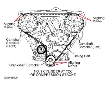
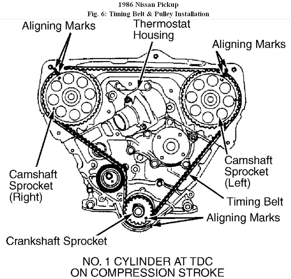
1. Ensure number one cylinder is at TDC on compression stroke. Install crankshaft sprocket, oil pump drive gear and oil thrower (if removed). Mating marks on crankshaft sprocket must face front and large inner chamfered area of oil pump drive gear must face engine rear.

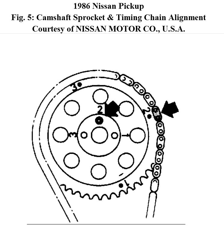
2. Place timing chain on camshaft sprocket. One silver colored link on chain must be aligned with number two dot on outer camshaft sprocket. The second silver link on chain must align with dot on crankshaft sprocket.

3. Install camshaft sprocket and timing chain. Ensure number two hole on camshaft sprocket is fitted to camshaft knock pin. Install timing chain guide and tension-er on right side of timing chain. Ensure chain guide is installed tight against chain.

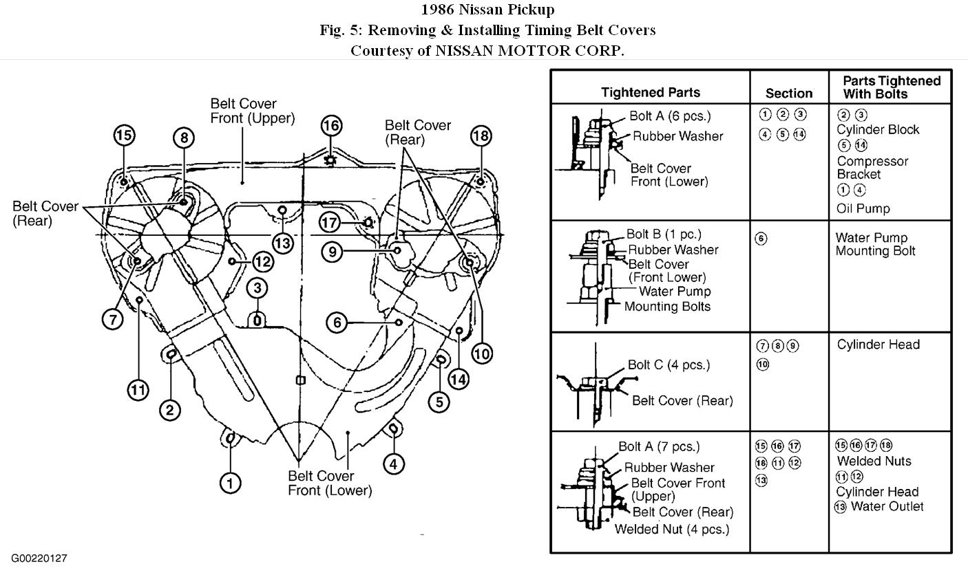
4. Install chain guide on left side of timing chain. Adjust the protrusion of chain tension-er and chain guide to zero. To complete installation, reverse removal procedure. With components installed, slowly rotate crankshaft to ensure pistons do not interfere with valves.

The so called silver links could be slightly darker in shade. I they are covered in oil, it would be difficult to distinguish, wipe them clean and dry and you should be able to differentiate.

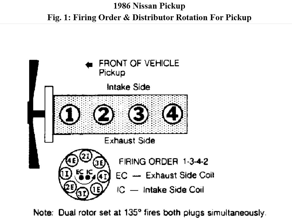
I could not find any reference on the distributor installation but what you have would mean the distributor is 180 degrees off. Before you do anything, ensure the number four cylinder valve are overlapped.

TDC can mean beginning of compression or intake stroke.

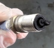
If markings are correct and distributor needs to be reinstalled, pull it out. There is a punxh mark on the distributor end gear. On housing there is a detent or triangular arrow mark. Match the two points and you have the rotor at number one firing position. Plug distributor in, remember to note the position of the holding bolt. The rotor would turn slightly when it goes in due to the gear sliding in.
With number one cylinder at TDC on compression stroke.
Was this
answer
helpful?
Yes
No
+25
Wednesday, July 29th, 2020 AT 1:40 PM (Merged)
Tiny
KHLOW2008
  • MECHANIC
  • 41,815 POSTS
One more diagram for you.
Was this
answer
helpful?
Yes
No
+30
Wednesday, July 29th, 2020 AT 1:40 PM (Merged)
Tiny
CRAIGCOOPER
  • MEMBER
  • 2 POSTS
First off, I thank you for your help. It wont be until this weekend until I get back to it. I do know that the wiring diagram you provided is different than the Chilton manual. It shows number one intake to be where your diagram shows number 4E to be. Is it possible someone has rewired the distributor previously, and I am paranoid? Because as I have it, I could not feel any valve to piston interference. I have compression, both intake and exhaust valves are closed, and according to the diagram you provided, this engine, the rotor points toward 2E and that is where the number elevn wire is at.
Was this
answer
helpful?
Yes
No
+5
Wednesday, July 29th, 2020 AT 1:40 PM (Merged)
Tiny
KHLOW2008
  • MECHANIC
  • 41,815 POSTS
Guess someone had the timing wrong by a tooth or two and decided to change the location of the number one cylinder. It is okay, it would still work without any problem. Important thing is the timing chain is installed correctly.
Was this
answer
helpful?
Yes
No
+5
Wednesday, July 29th, 2020 AT 1:40 PM (Merged)
Tiny
2CP-ARCHIVES
  • MEMBER
  • 4,544 POSTS
  • 1988 NISSAN TRUCK
  • 300,000 MILES
Timing marks dont line up on camshaft pulley how can I correct this? Belt broke.
Was this
answer
helpful?
Yes
No
+1
Wednesday, July 29th, 2020 AT 1:40 PM (Merged)
Tiny
KHLOW2008
  • MECHANIC
  • 41,815 POSTS
You would need to run the camsnaft to get them right. Move piston away from TDC and get the camshaft timing correct before turning the crankshaft to TDC position.
Was this
answer
helpful?
Yes
No
Wednesday, July 29th, 2020 AT 1:40 PM (Merged)
Tiny
CHUCHO
  • MEMBER
  • 8 POSTS
  • 1986 NISSAN TRUCK
  • 6 CYL
  • AWD
  • MANUAL
How do I replace the timing belt on an 86 nissan pick up?
Was this
answer
helpful?
Yes
No
Wednesday, July 29th, 2020 AT 1:40 PM (Merged)
Tiny
KHLOW2008
  • MECHANIC
  • 41,815 POSTS
TIMING BELT
Removal

1. Release fuel pressure from fuel delivery system. Raise and support vehicle. Remove right wheel and engine side cover. Lower vehicle. Drain cooling system. Remove cooling fan duct. Remove engine coolant reservoir. Remove actuator. Remove radiator hoses.
DO NOT allow coolant to contact drive belts.

2. Remove front upper and lower belt covers. See Fig. 5. Remove drive belts. Set No. 1 cylinder at TDC of compression stroke. Remove idler bracket of compressor drive belt and crankshaft pulley. Remove timing belt by removing timing belt tensioner and return spring.

Installation

1. Confirm that piston No. 1 is at TDC of compression stroke. Remove valve covers and loosen all rocker shaft bolts. DO NOT bend timing belt. Install tensioner and return spring.

2. Turn tensioner clockwise and temporarily tighten lock nut. Install timing belt. Align White lines on timing belt with punch mark on camshaft pulleys and crankshaft pulley. Arrow on timing belt must be pointing toward front belt covers.

3. Slowly turn tensioner with Allen wrench clockwise and counterclockwise 2 or 3 times. When camshafts and crankshaft marks are aligned, tighten tensioner lock nut. See Fig. 6. Ensure that camshaft lobes are correctly positioned. Tighten rocker shaft bolts in 2 stages. To complete installation, reverse removal procedures.
Was this
answer
helpful?
Yes
No
+2
Wednesday, July 29th, 2020 AT 1:40 PM (Merged)

Please login or register to post a reply.

Sponsored links