Take it to a volvo tech need to have the correct scanner to get to the codes as an OBDII reader will not help
this is what i have on the subject
IMMOBILIZER TERMINALS, INTERMITTENT NO START
TECHNICAL SERVICE BULLETIN
When diagnosing an intermittent no start condition, the immobilizer system should be checked for DTC's. Immobilizer DTC's IMM-233, -234 or -321 may be stored in the control module memory due to incorrect terminal contact. To check the male/female pin contact for connector 4/22 and 7/39, proceed with the following instructions.
Checking/replacing the wire terminals on the immobilizer
Preparations
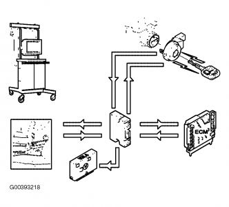
Read out diagnostic trouble codes (DTC's) (see Fig. 1 )
Connect the VADIS station.
Select vehicle communication.
Read out diagnostic trouble codes (DTC's) for the immobilizer system.
If any of the following diagnostic trouble codes (DTC) are stored, there may be poor contact between the wire terminals in the connector to 4/22 and 7/39.
233 = Antenna ring
234 = Transponder communication
321 = Initiation signal from the engine control module (ECM).
Remedy other diagnostic trouble codes (DTC's)
Fig. 1: Reading DTC'S
Removal
Removing the cover/panel
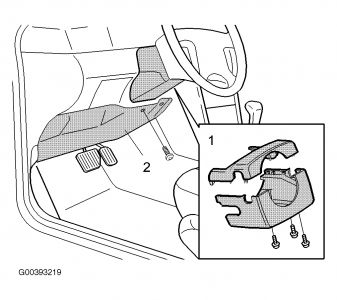
Remove cover/panel as per Fig. 2 .
Fig. 2: Removing Cover/Panel
Check the crimping of the wire terminals in the connectors (see Fig. 3 )
NOTE:Only connector 4/22 is shown. The secondary lock is the same for both connectors.
Remove the connectors for the antenna ring (7/39) and immobilizer control module ECU (4/22).
Open the secondary lock (1) on both the connectors.
Check so that all crimps on the wire terminals are intact.
Checking the female wire terminals in the connectors (see Fig. 3 )
Hint : Use a NEW MALE AND FEMALE wire terminal to get a feel of what the grip/clamp force should be with two new terminals. (P/N 978304 / 9187040)
Inspect all female wire terminals for any damages. Replace terminal(s) if damaged.
Probe all the female wire terminals in the connectors with the NEW male wire terminal to find out if any terminal has less clamp force compared to when trying out the two NEW terminals initially.
Replace the female wire terminal(s), which have less grip/clamp force.
Hint : If diagnostic trouble code (DTC) 321 is stored, it can be due to poor contact between terminals in the connector at the engine control module (ECM) (4/46). See VADIS for fault-tracing.
Fig. 3: Connectors
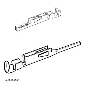
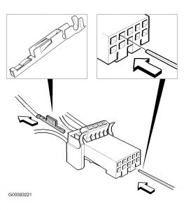
Replacing wire terminals (see Fig. 4 )
Use tool 951 2637 with a square point (1.2 x 1.2 mm).
Cut off the old wire terminal and strip off wire insulation.
Use lock crimp pliers with the red handles (9512648 socket A).
Crimp the new wire terminal.
Reinstall the wire terminal in connector ensuring correct positioning.
Fig. 4: Replacing Wire Terminals
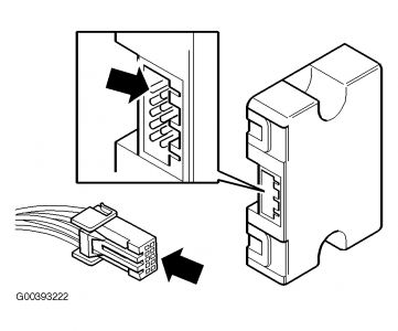
Check the terminal (see Fig. 5 )
Check that the terminals are not bent or damaged on the ECU (4/22) and on the antenna ring (7/39).
Reconnect the connector.
Fig. 5: Checking Terminal
Erasing trouble codes
Erase the stored trouble codes after carrying out the repair.
Test the function after completing work.
Reinstall the cover for the steering column and the panel under the dashboard.
SPONSORED LINKS
Friday, April 30th, 2010 AT 6:09 AM