2002 Saturn L100 Thermal Expansion Valve

Tiny
GMANPUMPS
  • MEMBER
  • 2002 SATURN L100
  • 4 CYL
  • FWD
  • AUTOMATIC
  • 107,000 MILES
Hi guys, I have either a thermal valve to evap coil leak or a evap coil leak. I have a new TXV but it is tough to know if I am installing it right. I understand there is a tool for this purpose. It is a sort of blind install as you cannot see the connection on the coil side to know if it right. Would you have some advice on installing the TXV? If indeed it is the coil, and I know it is a big job, any advice on the dash teardown? Any help is greatly appreciated. GW
Monday, October 19th, 2009 AT 8:04 AM

3 Replies

Tiny
BMRFIXIT
  • MECHANIC
  • 19,053 POSTS
I ve never done one but I figgered i ll offer you what my book say on the supject hope it will help

THERMAL EXPANSION VALVE
CAUTION:Cap or tape open A/C hoses and A/C refrigerant components immediately to prevent A/C system contamination. Use only Polyalkylene Glycol Synthetic Refrigerant Oil (PAG) for internal circulation through the R-134a A/C system and only 525 viscosity mineral oil on fitting threads and "O" rings. If lubricants other than those specified are used, compressor failure and/or fitting seizure may result.

CAUTION:When removing the TXV, keep dirt and foreign material form getting on or in the "O" ring sealing surfaces. Clean tools and a clean work area are important for proper service. The TXV seal area should be cleaned before any repairs are performed. The parts must be kept clean at all times and any parts to be assembled should be cleaned with a non-petroleum based solvent and dried with air. Use only lint free cloths to wipe parts. Do not allow solvent to enter evaporator or hose.

NOTE:Tools Required: ACR 2000 Air Conditioning Service Center (J-43600) and TXV Installation Tool (J-44655).

Removal
Disconnect negative battery cable. Recover refrigerant. See RECOVERY, EVACUATION & RECHARGING in GENERAL SERVICING PROCEDURES article in GENERAL SERVICING. Measure amount of oil removed during recovery process.
NOTE:Earlier vehicles used a bolt instead of a stud and nut.

Remove suction/liquid line assembly to Thermal Expansion Valve (TXV) retaining nut. Remove suction/liquid line assembly block from TXV by gently rocking while pulling forward.
Remove TXV-to-evaporator core bolts.
On earlier vehicles, install suction/liquid line assembly-to-TXV bolt hand tight into TXV. Using bolt or stud as a handle, remove TXV from evaporator core by gently rocking TXV while pulling forward.

Using your fingers or a plastic tool, remove "O" rings from evaporator core pipes.
Use a mirror to view "O" rings on evaporator core.
Installation
Lubricate and install NEW "O" rings on evaporator core pipes.
Install TXV using TXV Installation Tool to support evaporator core pipes and mounting flange while installing TXV.
Orient TXV with dome-shaped end toward passenger side of vehicle.
Install cap screws through T-handle and through TXV.
Thread cap screws into evaporative core flange.
Pull T-handle back against cap screws and carefully install and seat TXV into position.
Carefully remove cap screws and T-handle.

Apply a thin coating of clean mineral oil on TXV to evaporator "O" ring surfaces. Make sure TXV is completely installed. When properly installed, TXV should be almost flush with the beveled edge of the TXV foam seal.
Thread TXV-to-evaporator core block bolts into the block by hand. Bolts should thread in easily. Do not use force. If bolts do not thread in easily, verify that TXV is properly installed onto both pipes and fully seated to block.
NOTE:Earlier vehicles used a bolt instead of a stud/nut.

Remove cap or tape from suction/liquid line assembly block. Thoroughly clean "O" ring surfaces. Lubricate and install NEW "O" rings on suction/liquid line assembly block. Install suction/liquid line assembly block to TXV.
Install suction/liquid line assembly to TXV nut and tighten to specification


https://www.2carpros.com/forum/automotive_pictures/99387_Graphic1_561.jpg


https://www.2carpros.com/forum/automotive_pictures/99387_Graphic2_270.jpg

Was this
answer
helpful?
Yes
No
Tuesday, October 20th, 2009 AT 9:51 PM
Tiny
GMANPUMPS
  • MEMBER
  • 2 POSTS
The thermal expansion valve wasn't hard to remove but it looks like the connection to the evap coil has broken down? Almost like some movement of the coil or txv has worn a hole in the connection. Anyone know if there is a sealant of sorts that can be used? If not, can anyone forward me the dash breakdown to get to the coil. I know it is a big job, but as this has become a project car, it may be worth a shot. Thanks for the help. Gman
Was this
answer
helpful?
Yes
No
Friday, October 23rd, 2009 AT 10:35 AM
Tiny
BMRFIXIT
  • MECHANIC
  • 19,053 POSTS
This is what my book have on it hope it help
good luck

EVAPORATOR
CAUTION:When cutting open evaporator access door, avoid cutting internal components. Cut only inside raised bead area. Do not cut through or damage raised bead, this bead will be used as a sealing surface when completing the procedure.

CAUTION:Cap or tape open A/C hoses and A/C refrigerant components immediately to prevent A/C system contamination. Use only Polyalkylene Glycol Synthetic Refrigerant Oil (PAG) for internal circulation through the R-134a A/C system and only 525 viscosity mineral oil on fitting threads and "O" rings. If lubricants other than those specified are used, compressor failure and/or fitting seizure may result.

Removal
Turn ignition ON and select outside air on control head. Disconnect negative battery cable. Recover refrigerant. See RECOVERY, EVACUATION & RECHARGING in GENERAL SERVICING PROCEDURES article in GENERAL SERVICING. Measure amount of oil removed during recovery process.
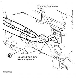
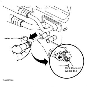
Remove Thermal Expansion Valve (TXV.
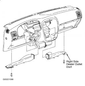
Disconnect negative battery cable. Open glove compartment door and remove glove compartment lamp assembly by pulling on lamp plunger. Disconnect glove compartment lamp wiring harness from glove compartment lamp. Remove right side Instrument Panel (I/P) lower dash insulator retainers. Pull insulator rearward to detach the insulator from forward insulator retainers. Remove right side heater outlet assembly retainer and remove outlet.
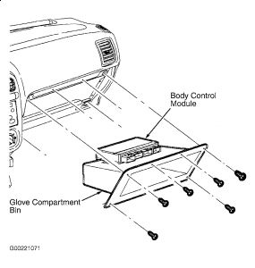
Remove glove compartment door. Remove glove compartment bin fasteners and slowly remove glove compartment bin tilting bin downward to expose the Body Control Module (BCM) residing on top of glove compartment. Remove the BCM from glove compartment by sliding module out of attaching slots. Remove glove compartment bin..
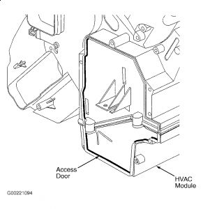
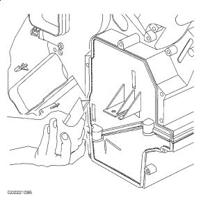
Locate evaporator access door location on right side of the module. Entire area inside raised lip is to be cut out.
Using a sharp utility knife, cut through module wall, following inside of raised bead as a guide. Several passes may be necessary to accomplish this..
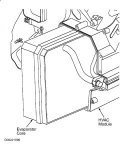
From inside of vehicle, slide evaporator core out through access door opening. Use care not to damage core fins or pipes.
Carefully clean out any debris that may be inside of module.
Installation
Add amount of compressor oil that was removed during discharge to evaporator core. If a NEW evaporator core is being installed, add appropriate amount of compressor oil to system for evaporator core being replaced. See SPECIFICATIONS .
Carefully install evaporator into module, making sure not to bend pipes or damage foam seals.
Inspect module/TXV foam seal to verify proper location. Install TXV.

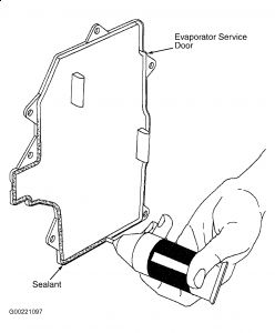
NOTE:Proper sealing is important to prevent condensation from leaking into the passenger compartment.

Apply sealant provided in service kit around perimeter of evaporator core service door tongue and groove location.
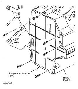
Install evaporator core service door to module and install screws.
Tighten to specification

Install glove compartment bin partially into opening and secure BCM module to glove compartment bin slots.
Route glove compartment lamp wiring harness through lamp opening and install glove compartment bin to I/P. Install and tighten glove compartment screws to specification. Connect glove compartment lamp wiring harness to glove compartment lamp and snap lamp into glove compartment bin.
Install right side heater outlet duct with retainer. Install lower dash insulator with retainers.
Install glove compartment door and fasteners. Tighten glove compartment door fasteners to specification. Connect negative battery cable and check for proper alignment of glove compartment door and function of glove compartment lamp.
Evacuate and recharge A/C system
. Ensure A/C system is operating properly.
Turn HVAC blower on with mode set to HEATER, temperature on HOT, recirculation on OUTSIDE AIR. Use the back of your hand to check for any air leaks around service door. If any leaks are detected, door must be removed and resealed.


https://www.2carpros.com/forum/automotive_pictures/99387_Graphic1_569.jpg


https://www.2carpros.com/forum/automotive_pictures/99387_Graphic2_274.jpg


https://www.2carpros.com/forum/automotive_pictures/99387_Graphic3_124.jpg


https://www.2carpros.com/forum/automotive_pictures/99387_Graphic4_55.jpg


https://www.2carpros.com/forum/automotive_pictures/99387_Graphic5_32.jpg


https://www.2carpros.com/forum/automotive_pictures/99387_Graphic5_33.jpg


https://www.2carpros.com/forum/automotive_pictures/99387_Graphic6_21.jpg


https://www.2carpros.com/forum/automotive_pictures/99387_Graphic7_16.jpg

Was this
answer
helpful?
Yes
No
+2
Friday, October 23rd, 2009 AT 1:11 PM

Please login or register to post a reply.

Sponsored links