Blower motor runs constantly

Tiny
TOM CAREY
  • MEMBER
  • 1999 SAAB 9-3
  • 4 CYL
  • FWD
  • MANUAL
  • 61,000 MILES
I have a 99 saab 9-3se with automatic climate control. The blower motor runs all the time so I had to pull the fuse to stop the motor from running. I replaced the resistor on the motor and it still continues to run so I guess I have to replace the ACC module. The part is mounted on the evaporator according to the su[[lier, but where is the evaporator located and what is the easiest way to get to the evaporator to replace the acc module
Sunday, April 25th, 2010 AT 2:34 PM

11 Replies

Tiny
DAVE H
  • MECHANIC
  • 13,383 POSTS
Hello .. thanks for the donation .. much appreciated

I would check for fault codes before replacing this expensive control module.. it could be a fault on the speed control unit ?

RETRIEVING DIAGNOSTIC TROUBLE CODES
During ACC control module calibration any stored and/or detected DTCs will be displayed in place of temperature. A number from 0-23 will be displayed for approximately 3 seconds each. Fan speed bars are used to indicate the number of DTCs stored. A maximum of 6 DTCs can be stored at any time. See ACC CONTROL MODULE DTCs.
Connect Saab Tech 2 or OBD-II compliant scan tool to Data Link Connector (DLC). DLC is located under instrument panel, below steering column. Turn ignition on. Following scan tool manufacturer's instructions, read and note DTCs. See ACC CONTROL MODULE DTCs and DICE CONTROL MODULE DTCs tables.
Because a functional problem in one system can be caused from a problem in another system it is important to read DTCs from all vehicle systems. Compare DTCs with customer complaint. DTC that most closely corresponds with customer complaint is probably caused by primary malfunction.

CONTROL MODULES
Manufacturer has found many control modules that have been replaced were not the cause of the problem and replacement of the control module did not correct the problem. Upon examination, these control modules were found to be free of defects. Before replacing a suspect control module, preform the following:
Before replacing ACC control module, ensure that all user-programming has been cleared. See ACC CONTROL MODULE PROGRAMMING under PROGRAMMING.

DTC B2425: FAN BLOWER MOTOR CONTROL VOLTAGE
Fault Symptoms
Fan blower motor cannot be operated from ACC control panel.
Fault Conditions
A DTC will set if a short to ground or battery voltage is detected.
Diagnostic Procedure
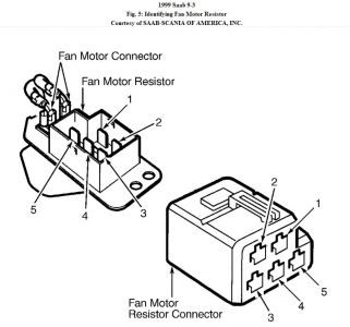
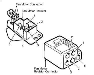
Disconnect fan blower motor control module 8-pin connector located on right side of climate control unit. See Fig. 2. Measure voltage between ground and fan blower motor control module 8-pin connector terminal No. 8 (Gray/Red wire). Turn ignition on. Using fan blower motor speed control buttons on ACC control panel, increase blower motor speed in steps. If voltage is 0.0-5.0 volts in short steps from minimum to maximum blower motor speed, replace blower motor control module. If voltage is not as specified, repair open or short in Gray/Red wire between fan blower motor control module and ACC control module 39-pin connector terminal No. 14. See Fig. 4. See WIRING DIAGRAMS. When repairs are completed, go to next step.
Using scan tool, clear all DTCs from all systems. Recheck A/C system operation for original complaint. If A/C system is operating properly and no DTC has been detected, repair is complete. If a DTC has been detected, a control module may need to be replaced. See CONTROL MODULES under TESTING.

FAN BLOWER MOTOR SPEED CONTROL UNIT
Removal & Installation
NOTE:DO NOT use aluminum spacer supplied with fan blower motor speed control unit.

Remove glove box. Remove trim panel from right side of center console. Remove floor air duct. Remove fan speed control unit protective cover. Remove fan speed control unit retaining screws and control unit. See Fig. 2. Disconnect wiring harness from unit.
To install, reverse removal procedure. Remove old silicon paste from control module contact surface on climate control unit. Apply a thin coating of Silicon Paste (30 07 895) to fan speed control unit mounting surface. Install fan speed control unit ensuring that both sleeves are inserted into climate control unit holes. Calibrate ACC control module. See ACC CONTROL MODULE CALIBRATION under PROGRAMMING.

ACC Control Module..Under radio.


https://www.2carpros.com/forum/automotive_pictures/266999_saab_8.jpg


Removal & Installation
Carefully pry out push buttons located directly below the ACC control module. Carefully press out ACC control module from behind. Disconnect wiring harness from ACC control module. To install, reverse removal procedure. Calibrate ACC control module. See ACC CONTROL MODULE CALIBRATION under PROGRAMMING.

Hope this helps


https://www.2carpros.com/forum/automotive_pictures/266999_AAA2_1136.png

Was this
answer
helpful?
Yes
No
Sunday, April 25th, 2010 AT 5:08 PM
Tiny
TOM CAREY
  • MEMBER
  • 3 POSTS
To dave h I forgot to say in my first question that I tried to recalibrate the acc contrl module by pressing the auto and the off buttons at the same time. I get an error code #02 and one bar on the fan sppeed indicator. This should norrow your answer a little. The acc control module that mounts on the evaporator according to the parts info is also the heater control, a/c fan speed control, and a/c fan resister. That why I thought replaceing this part would cover just about every thing
Was this
answer
helpful?
Yes
No
Tuesday, April 27th, 2010 AT 9:32 PM
Tiny
DAVE H
  • MECHANIC
  • 13,383 POSTS
Sorry for the delay in replying.

Fault code 02/DTC 1350: CABIN TEMPERATURE SENSOR
NOTE:DTC will be cleared after ignition has been turned on 20 times if no fault conditions are detected. DTC can be cleared using scan tool.

Fault Symptoms
Temperature in cabin may seem too hot or too cold in relation to selected temperature. When DTC sets, ACC control module will initially use ambient (outside) temperature as a default value when ignition is turned on. Default value used will then be a mean value of calculated temperatures at head height of front seats.
Fault Conditions
The following conditions may cause DTC to set:
Open circuit or a short to battery voltage. Voltage measured at ACC control module 39-pin connector terminal No. 20 (Blue/Yellow wire) will be more than 4.9 volts.
There is a short to ground. Voltage measured at 39-pin connector terminal No. 20 (Blue/Yellow wire) is less than 0.1 volt.
If there are 5 consecutive periods without a cabin temperature sensor signal. Every 440 milliseconds ACC control module looks for a cabin temperature sensor signal.
Diagnostic Procedure
Turn ignition off. Connect scan tool to Data Link Connector (DLC) located under steering column. Using scan tool, contact ACC control module and check for DTC B2945. If DTC B2945 is not displayed, go to next step. If DTC B2945 is displayed, go to DTC B2945: SENSOR GROUND.
Locate cabin temperature sensor in instrument panel below ACC panel and disconnect 4-pin connector. Connect a test light between battery voltage and cabin temperature sensor connector terminal No. 2 (Yellow/Brown wire). See WIRING DIAGRAMS. If test light illuminates, go to next step. If test light does not illuminate, repair Yellow/Brown wire between sensor and ACC control module 39-pin connector terminal No. 39. See Fig. 4. When repairs are complete, go to step 5.
Turn ignition on. Using scan tool, contact ACC control module and read cabin temperature sensor value. If value is 4.7-5.0 volts, go to next step. If value is not 4.7-5.0 volts, repair open in Blue/Yellow wire between sensor 4-pin connector terminal No. 3 and ACC control module connector terminal No. 20. When repairs are complete, go to step 5.
Connect a jumper wire between sensor 4-pin connector terminals No. 2 (Yellow/Brown wire) and No. 3 (Blue/Yellow wire). Using scan tool, contact ACC control module and read cabin temperature sensor value. If value is zero volts, replace cabin temperature sensor. If value is not zero volts, short in Blue/Yellow wire. When repairs are complete, go to next step.
Using scan tool, clear all DTCs from all systems. Recheck A/C system operation for original complaint. If A/C system is operating properly and no DTC has been detected, repair is complete. If a DTC has been detected, a control module may need to be replaced. See CONTROL MODULES under TESTING.
Was this
answer
helpful?
Yes
No
-1
Friday, April 30th, 2010 AT 3:03 AM
Tiny
ROB CLARK
  • MEMBER
  • 1 POST
  • 1999 SAAB 9-3
  • 4 CYL
  • 2WD
  • AUTOMATIC
  • 80,000 MILES
Is it ther fuse that causes my blower to stopped
Was this
answer
helpful?
Yes
No
Tuesday, November 12th, 2019 AT 6:30 PM (Merged)
Tiny
MERLIN2021
  • MECHANIC
  • 17,250 POSTS
This is for manual heater/ a/c system:
FAN (BLOWER) MOTOR DOES NOT OPERATE 1. Turn ignition on. Operate fan switch at each speed position. See Fig. 1 . If fan motor does not operate at any speed position, go to next step. If fan motor does not operate at speed position "1", go to step 6 . If fan motor does not operate at speed position "2", go to step 8 . If fan motor does not operate at speed position "3", go to step 10 . If fan motor does not operate at speed position "4", go to step 12 . 2. Turn ignition off. Check fuse No. 3 (30-amp) located in main fuse box, positioned at driver's end of instrument panel. If fuse is okay, go to next step. If fuse is blown, replace fuse and recheck fan motor operation. If fuse blows again, perform repairs as necessary. See WIRING DIAGRAMS . If fuse is okay, go to step 14 . 3. Turn ignition off. Disconnect fan motor switch 8-pin connector. Turn ignition on. Connect a test light between ground and fan switch harness connector terminal No. 2 (Red wire). See WIRING DIAGRAMS . If test light illuminates, go to next step. If test light does not illuminate, repair Red wire between fan switch and fuse No. 3. When repairs are complete, go to step 14 . 4. Turn ignition off. Locate fan motor resistor under intake air filter. Disconnect fan motor resistor 5-pin connector. See Fig. 5 . Connect a test light between battery voltage and harness side connector terminal No. 5 (Black wire). If test light comes on, go to next step. If test light does not come on, repair Black wire between fan motor resistor connector and ground connection. When repairs are complete, go to step 14 . 5. Using a heavy gauge, fused (30-amp) jumper wire, apply battery voltage to fan motor resistor terminal No. 3. Using another heavy gauge jumper wire, ground fan motor resistor terminal No. 5. If fan motor does not operate at full speed, check circuits between fan motor resistor and fan motor. If circuits are okay, replace fan motor. If fan motor operates at full speed, replace fan motor switch. When repairs are complete, go to step 14 . 6. Turn ignition off. Locate fan motor resistor under intake air filter. Disconnect fan motor resistor 5-pin connector. See Fig. 5 . Connect a test light between ground and fan motor resistor harness connector terminal No. 1 (Orange wire). Turn ignition on and fan switch to speed position "1". If test light does not come on, go to next step. If test light comes on, replace fan motor resistor. When repairs are complete, go to step 14 . 7. Check Orange wire circuit between fan motor resistor and fan motor speed switch. See WIRING DIAGRAMS . Repair circuit as necessary. If circuit is okay, replace fan motor resistor. When repairs are complete, go to step 14 . 8. Turn ignition off. Locate fan motor resistor under intake air filter. Disconnect fan motor resistor 5-pin connector. Connect a test light between ground and fan motor resistor harness connector terminal No. 2 (Yellow wire). Turn ignition on and fan switch to speed position "2". If test light does not come on, go to next step. If test light comes on, replace fan motor resistor. When repairs are complete, go to step 14 . 9. Check Yellow wire circuit between fan motor and fan motor switch. See WIRING DIAGRAMS . Repair circuit as necessary. If circuit is okay, replace fan motor resistor. When repairs are complete, go to step 14 . 10. Turn ignition off. Locate fan motor resistor under intake air filter. Disconnect fan motor resistor 5-pin connector. See Fig. 5 . Connect a test light between ground and fan motor NOTE: Because of fan motor high current requirements, use heavy gauge jumper wires when testing fan motor operation. resistor harness connector terminal No. 4 (Green wire). Turn ignition on and fan switch to speed position "3". If test light does not come on, go to next step. If test light comes on, replace fan motor resistor. When repairs are complete, go to step 14 . 11. Check Green wire circuit between fan motor resistor and fan motor switch. See WIRING DIAGRAMS . Repair circuit as necessary. If circuit is okay, replace fan motor resistor. When repairs are complete, go to step 14 . 12. Turn ignition off. Locate fan motor resistor under intake air filter. Disconnect fan motor resistor 5-pin connector. Connect a test light between ground and fan motor resistor harness connector terminal No. 3 (White wire). Turn ignition on and fan switch to speed position "4". If test light does not come on, go to next step. If test light comes on, replace fan motor resistor. When repairs are complete, go to step 14 . 13. Check White wire circuit between fan motor resistor and fan switch. See WIRING DIAGRAMS . Repair circuit as necessary. If circuit is okay, replace fan motor resistor. When repairs are complete, go to next step. 14. Using scan tool clear DTCs from all systems. Check A/C system operation. If A/C system operates properly, inspection is complete. If A/C system does not operate properly, go to CONTROL MODULES under TESTING.


https://www.2carpros.com/forum/automotive_pictures/62217_BMR_5.jpg

Was this
answer
helpful?
Yes
No
Tuesday, November 12th, 2019 AT 6:30 PM (Merged)
Tiny
MNTHNY4
  • MECHANIC
  • 612 POSTS
Firstly do u have a manual control panel [MCC]or a automatic control panel [ACC], if acc type replace your fanspeed control unit located on the passenger side mounted to ac heater box, if mcc type replace your fan speed resistor, located under the crowl cover where fan motor in fitted, note if mcc type, remove control unit & check if fan speed switch section is burnt from the back if so, then replace panel first. GOOD LUCK.
Was this
answer
helpful?
Yes
No
Tuesday, November 12th, 2019 AT 6:30 PM (Merged)
Tiny
MERLIN2021
  • MECHANIC
  • 17,250 POSTS
Thanks for the assist.
Was this
answer
helpful?
Yes
No
Tuesday, November 12th, 2019 AT 6:30 PM (Merged)
Tiny
JONATHAN.GOODWIN
  • MEMBER
  • 1 POST
What is the part number or the name of the female connect/plug that is in the picture. It is labeled Fan Motor Resistor Connector.
I need a new connector and wiring harness that connects to the Blower Resistor but can't find it anywhere for a MCC climate control system on a 1999 Saab 9-3.
Was this
answer
helpful?
Yes
No
Tuesday, November 12th, 2019 AT 6:30 PM (Merged)
Tiny
NBMEDIC
  • MEMBER
  • 1 POST
When replacing my resistor the wires in the resistor connector came out of the harness. There is a red, black and orange/white wires? What numbers in the connector do these wires go to match up with the numbers in the resistor?
Was this
answer
helpful?
Yes
No
Tuesday, November 12th, 2019 AT 6:30 PM (Merged)
Tiny
DCROSKEY
  • MEMBER
  • 1 POST
  • 1999 SAAB 9-3
  • 4 CYL
  • FWD
  • AUTOMATIC
  • 145,096 MILES
I just bought a new blower and it is still not working is there another part connected to the blower that may have went out like a condutor or switch that I also need to buy and change, or could it be a electrical problem connecting to the blower.
Was this
answer
helpful?
Yes
No
Tuesday, November 12th, 2019 AT 6:30 PM (Merged)
Tiny
MERLIN2021
  • MECHANIC
  • 17,250 POSTS
FAN (BLOWER) MOTOR RESISTOR Removal & Installation Remove wiper arms. Remove cover over bulkhead and water deflector. Remove wiper unit. Remove air/pollen filter. Disconnect fan motor connector. Remove air/pollen filter frame. Remove screw securing fan motor resistor. Remove fan motor resistor. To install, reverse removal procedure. Ensure electrical wires are not pinched. Usually the weakest link is the resistor. If you get this far, before you remove the resistor, turn on blower, use a voltmeter at the blower connection, if there is power, motor could be NG.


https://www.2carpros.com/forum/automotive_pictures/62217_Saaba_1.jpg

Was this
answer
helpful?
Yes
No
Tuesday, November 12th, 2019 AT 6:30 PM (Merged)

Please login or register to post a reply.

Sponsored links